Operation exhaust gas recirculation (usa)
|
|
|||
|
14—050 Operation exhaust gas recirculation (usa)
|
|||
|
|
|||
|
A. General information
|
|||
|
|
|||
|
In (usa) version starting model year 1980 for California and starting model year 1981 for Federal and California, engine 617.95 is provided with exhaust gas recirculation (EGR).
To reduce nitric oxides in exhaust gases, a portion of the exhaust gases is returned from exhaust manifold to intake manifold by means of a valve.
The returned exhaust gas is vacuum-controlled by means of the accelerator pedal (depending on load) or is turned off at given driving conditions.
EGR has no influence on driving characteristics.
|
|||
|
|
|||
|
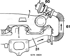
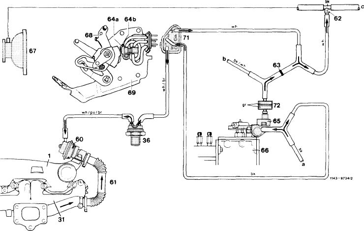
Operational diagram EGR
1 Intake manifold 31 Exhaust manifold
60 EGR valve
61 Corrugated tubing
|
 |
||
|
|
|||
|
14.8-050/1 USA F 3
|
|||
|
|
|||
|
|
|||
|
B. EGR components
|
|||
|
|
|||
|
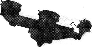
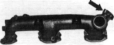
Exhaust manifold
The exhaust manifold is provided with a connection (arrow) for tapping the exhaust gases about to be recirculated.
|
 |
||
|
|
|||
|
147-17010
|
|||
|
|
|||
|
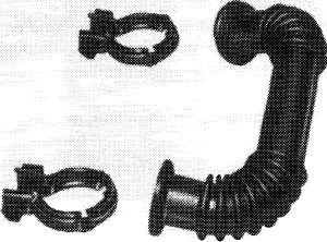
Corrugated tubing
A corrugated tube is installed between exhaust manifold and EGR valve, through which the exhaust gases are routed from exhaust manifold to EGR valve.
|
 |
||
|
|
|||
|
107-17022
|
|||
|
|
|||
|
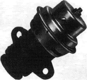
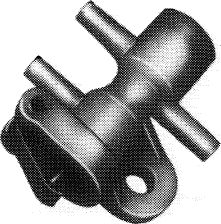
EGR valve
The EGR valve is flanged to intake manifold and controls the quantity of the returned exhaust gases depending on operating conditions.
|
 |
||
|
|
|||
|
Intake manifold
The intake manifold is provided with a two-hole flange (arrow) for attaching EGR valve. The recirculated exhaust gases are distributed to the individual cylinders.
|
 |
||
|
|
|||
|
107-17021
|
|||
|
|
|||
|
14.8-050/2 USA
|
|||
|
|
|||
|
|
|||
|
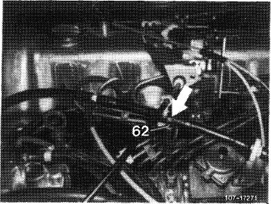
Vacuum tapping point with orifice (62, color code black)
The vacuum for controlling EGR is taken from vacuum line between vacuum pump and brake booster (arrow). The tapping point has a black orifice (62) with an ID of 0.6 mm (not exchangeable).
|
 |
||
|
|
|||
|
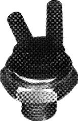
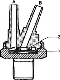
Thermovalve 40 °C (color code blue)
The thermovalve is screwed into thermostat housing. The designation „50 AB 5” is punched into metal part.
Below 40 °C/104 °F coolant temperature the bimetallic plate rests against O-ring and closes connection „B”.
Starting at approx. 40 °C/104 °F coolant temperature the bimetallic plate will snap in downward direction under influence of heat. Both connections are connected to each other.
The vacuum line (white/brown) to distributor should be plugged to connection „B”, since this alone will guarantee perfect sealing between bimetallic plate and O-ring.
|
 |
||
|
107-10895
|
|||
|
1074-WB9/1
|
|||
|
1 Bimetallic plate
2 O-ring
A To switchover valve (64a)
B To distributor (vacuum)
|
|||
|
|
|||
|
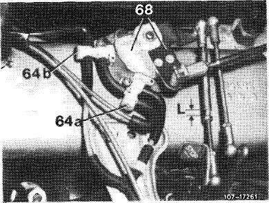
Switchover valve (64a, model year 1980)
The switchover valve is switched via guide lever (68) and cam.
The valve serves the purpose of venting the vacuum line to EGR valve for the purpose of switching off EGR at idle (throttle) linkage against idle speed stop).
|
 |
||
|
|
|||
|
14.8-050/3 USA F 3
|
|||
|
|
|||
|
|
|||
|
If the throttle linkage is actuated to the extent that the idle path (L) at idle path rod is bridged, the switchover valve has switched over and the largest possible EGR will proceed.
|
 |
||
|
Switchover valve (64b)
The switchover valve is switched over by the second cam on guide lever (68) shortly before attaining full throttle position. As a result, the vacuum line (white/ purple/brown) to EGR valve will be vented and there will be no EGR.
Attention!
The link and the cam running surface should be clean and not lubricated. They should be covered during engine preservation.
Note: At idle position (without idle path bridge „L”) both switchover valves may have passage from 2 to 5 only. With switchover valves switched through, passage should be available from 3 to 5.
|
|||
 |
|||
|
|
|||
|
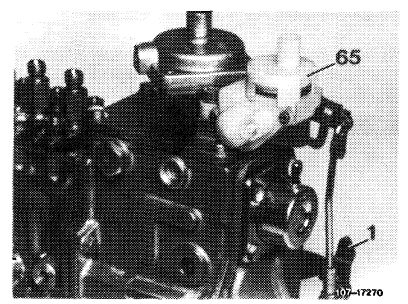
Switchover valves (model year 1981)
To control EGR, the switchover valves known from model year 1980 are used again, but their arrangement has been modified. Both switchover valves are now located on valve plate one above the other. Connection is made by a central plug (71). A cover plate is attached to prevent dirt collecting on plastic running surface.
|
 |
||
|
|
|||
|
W-1705S
|
|||
|
|
|||
|
64a Switchover valve idle shutoff — EGR
64b Switchover valve full throttle shutoff — EGR
68 Guide lever
71 Central plug
|
 |
||
|
|
|||
|
14.8-050/4 USA F3
|
|||
|
|
|||
|
|
|||||||||||||||||||||||||||||||||||||
|
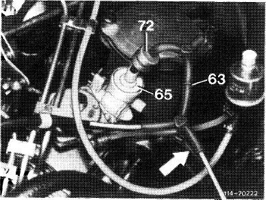
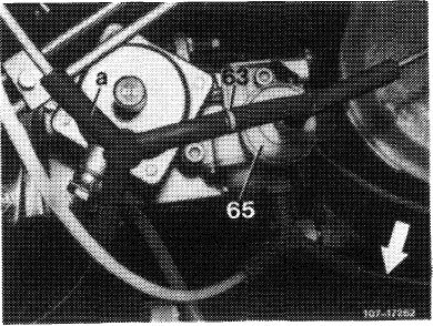
Orifice (63)
|
|||||||||||||||||||||||||||||||||||||
|
|
|||||||||||||||||||||||||||||||||||||
|
Orifices of different diameter may be installed between the two distributors on vacuum control valve (65).
|
 |
||||||||||||||||||||||||||||||||||||
|
Color code and diameter of orifices
|
|||||||||||||||||||||||||||||||||||||
|
|||||||||||||||||||||||||||||||||||||
|
107-17058
|
|||||||||||||||||||||||||||||||||||||
|
|
|||||||||||||||||||||||||||||||||||||
|
The ID of the orifice depends on the tolerances of the adjusting angle on regulating lever (1) of injection pump and vacuum control valve (65).
|
 |
||||||||||||||||||||||||||||||||||||
|
Model year 1980
|
|||||||||||||||||||||||||||||||||||||
|
|
|||||||||||||||||||||||||||||||||||||
|
Model year 1981
|
 |
||||||||||||||||||||||||||||||||||||
|
|
|||||||||||||||||||||||||||||||||||||
|
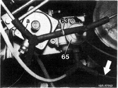
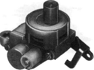
Vacuum control valve (65)
The vacuum control valve serves to control venting of EGR valve. At idle, the vacuum line to automatic transmission, to thermovalve 40 °C/104 °F and switchover valve (64a) is constantly vented by way of a small annular gap in vacuum control valve. The vacuum amounts to approx. 350—500 mbar.
|
 |
||||||||||||||||||||||||||||||||||||
|
|
|||||||||||||||||||||||||||||||||||||
|
14.8-050/5 USA F 3
|
|||||||||||||||||||||||||||||||||||||
|
|
|||||||||||||||||||||||||||||||||||||
|
|
|||
|
After bridging the idle path, the vent cross section in vacuum control valve is constantly increased under the increasing load and the vacuum is therefore continuously reduced. Venting proceeds via black plastic line (arrow) leading into passenger compartment.
|
 |
||
|
|
|||
|
107-17057
|
|||
|
|
|||
|
Model year 1980
|
 |
||
|
|
|||
|
Model year 1981
|
 |
||
|
|
|||
|
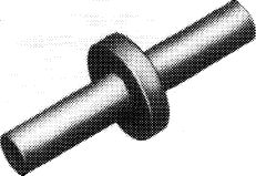
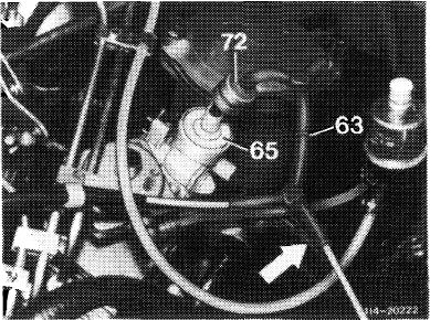
Damper (vacuum, 72) model year 1981 only
To reduce the high vacuum peaks, a damper is installed into vacuum line from vacuum control valve to central plug (valve plate).
|
|||
|
|
|||
|
14.8-050/6 USA F2
|
|||
|
|
|||
|
|
|||||||||||||||||||||||||||||||||||||||||||||||||||||||||||||||||||||||||||||||||||
|
C. Total operation (©) model year 1980
|
|||||||||||||||||||||||||||||||||||||||||||||||||||||||||||||||||||||||||||||||||||
|
|
|||||||||||||||||||||||||||||||||||||||||||||||||||||||||||||||||||||||||||||||||||
|
EGR begins:
• Above approx. 40 °C/104 °F coolant temperature: After the free travel of the free travel rod has been eliminated.
In partial load range up to final EGR shutoff shortly before full throttle stop.
Below approx. 40 °C/104 °F coolant temperature the thermovalve (36) is closed. The vacuum cannot move to EGR valve. There will be no EGR.
|
Starting at a coolant temperature of approx. 40 C/ 104 °F the thermovalve (36) opens. The vacuum, at idle 350—500 mbar, moves to the switchover valve (64a).
If the control linkage is at the idle speed stop, the EGR valve (60) is vented externally. There will be no EGR.
|
||||||||||||||||||||||||||||||||||||||||||||||||||||||||||||||||||||||||||||||||||
|
|
|||||||||||||||||||||||||||||||||||||||||||||||||||||||||||||||||||||||||||||||||||
 |
|||||||||||||||||||||||||||||||||||||||||||||||||||||||||||||||||||||||||||||||||||
|
|
|||||||||||||||||||||||||||||||||||||||||||||||||||||||||||||||||||||||||||||||||||
|
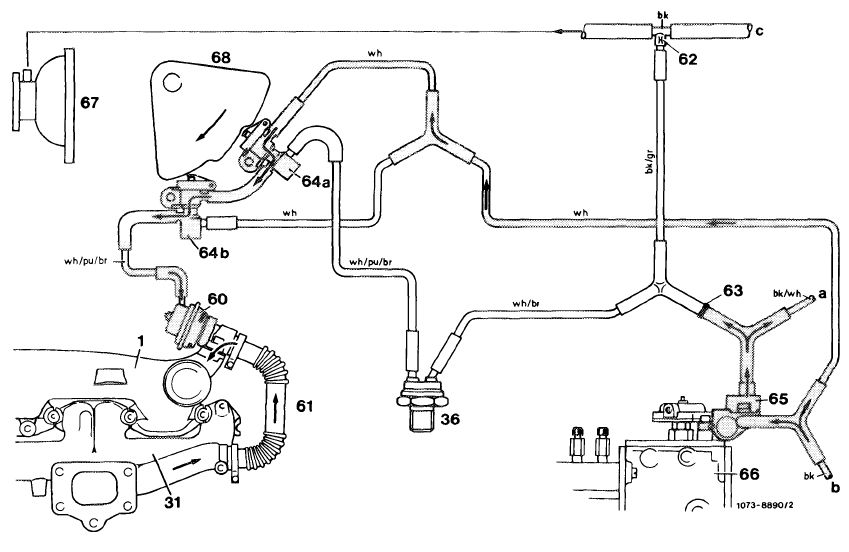
Vaccum routing at idle, throttle linkage at idle speed stop
|
|||||||||||||||||||||||||||||||||||||||||||||||||||||||||||||||||||||||||||||||||||
|
|
|||||||||||||||||||||||||||||||||||||||||||||||||||||||||||||||||||||||||||||||||||
|
|||||||||||||||||||||||||||||||||||||||||||||||||||||||||||||||||||||||||||||||||||
|
|
|||||||||||||||||||||||||||||||||||||||||||||||||||||||||||||||||||||||||||||||||||
|
64b Switchover valve, full throttle shutoff — EGR
|
|||||||||||||||||||||||||||||||||||||||||||||||||||||||||||||||||||||||||||||||||||
|
|
|||||||||||||||||||||||||||||||||||||||||||||||||||||||||||||||||||||||||||||||||||
|
14.8-050/7 USA F3
|
|||||||||||||||||||||||||||||||||||||||||||||||||||||||||||||||||||||||||||||||||||
|
|
|||||||||||||||||||||||||||||||||||||||||||||||||||||||||||||||||||||||||||||||||||
|
|
|||||
|
If the throttle linkage is opened so that the free travel in the free travel rod is eliminated, the switchover valve (64a) is operated by the cam of the guide lever (68). The vacuum now moves via the two switchover valves (64a and 64b) to the EGR valve and opens the valve completely. This results in max. possible EGR.
|
|||||
|
|
|||||
 |
|||||
|
|
|||||
|
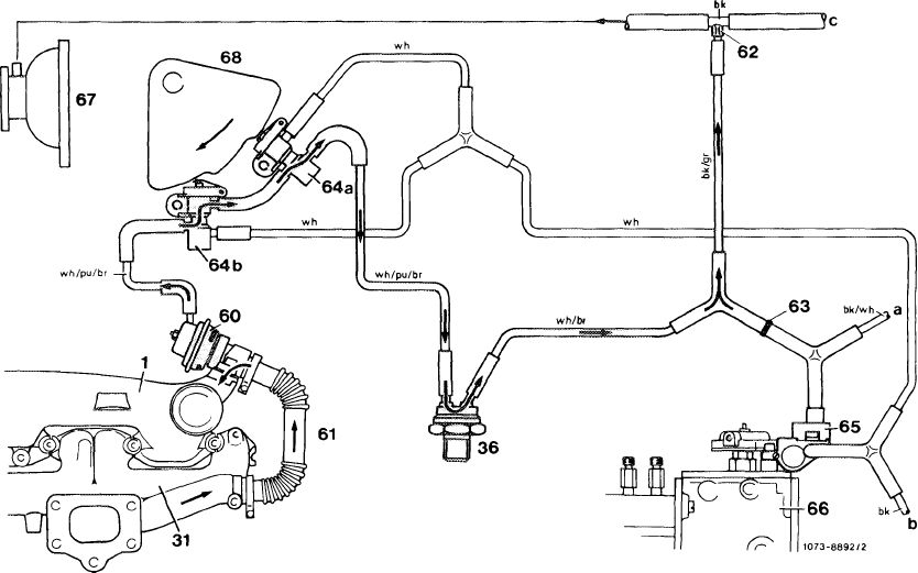
Vacuum routing after eliminating free travel
|
|||||
|
|
|||||
|
1
31 36 60 61
|
Intake manifold
Exhaust manifold
Thermovalve40oC/104°F
Exhaust gas recirculation valve (EGR)
Corrugated tubing
|
65 Vacuum control valve
66 Injection pump
67 Vacuum pump
68 Guide lever with cam
a Automatic transmission
b Vent to passenger compartment
c Brake unit
|
bk = black
br = brown
gr = green
pu = purple
re = red
wh = white
|
||
|
62 63
|
Orifice Orifice
|
||||
|
64a Switchover valve, idle speed shutoff — EGR 64b Switchover valve, full throttle shutoff — EGR
|
|||||
|
|
|||||
|
14.8-050/8 USA 1980 F3
|
|||||
|
|
|||||
|
|
||||
|
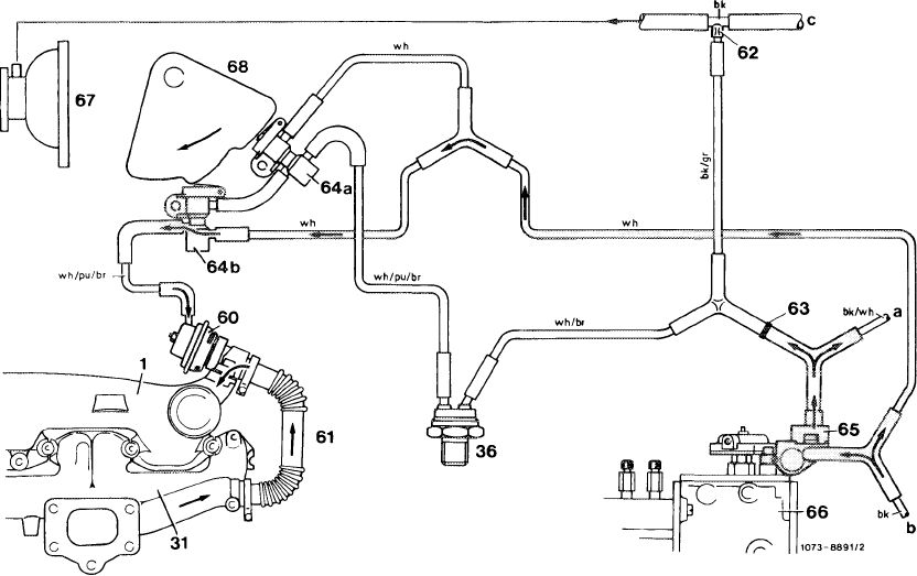
At increasing load the vacuum is gradually decreased via vacuum control valve (65). This also reduces the amount of recirculated exhaust gas. Shortly before reaching full throttle position, the switchover valve (64b) is vented to atmosphere via cam of guide lever (68). The vacuum is completely removed, there is no EGR.
|
||||
|
|
||||
 |
||||
|
|
||||
|
Venting process in full throttle position
1 Intake manifold
31 Exhaust manifold
36 Thermovalve 40 °C/104 °F
60 Exhaust gas recirculation valve (EGR)
61 Corrugated tubing
62 Orifice
63 Orifice
64a Switchover valve, idle speed shutoff — EGR 64b Switchover valve, full throttle shutoff — EGR
|
65 Vacuum control valve
66 Injection pump
67 Vacuum pump
68 Guide lever with cam
a Automatic transmission
b Vent to passenger compartment
c Brake unit
|
bk = black br = brown gr = green pu = purple re = red wh = white
|
||
|
|
||||
|
14.8-050/9 USA 1980 F 3
|
||||
|
|
||||
|
|
||||||||||||||||||||||||||||||||||||||||||||||||||||||||||||||||||||||
|
Total operation <@) starting model year 1981
EGR begins above approx. 40 °C/104 °F coolant temperature after free travel of free travel rod is eliminated, EGR takes place in total partial load range.
Starting at a coolant temperature of approx. 40 °C7 104 °F the thermovalve (36) opens. The vacuum, at idle 350—500 mbar, moves to switchover valve (64a).
If the control linkage is at idle speed stop, the EGR valve (60) is vented externally. There is no EGR.
|
If the throttle linkage is opened so that the free travel in the free travel rod is eliminated, the switchover valve (64a) is switched over by the cam of guide lever (68). The vacuum now moves via the two switchover valves (64a and 64b) to EGR valve and opens the valve completely. This results in max. possible EGR.
|
|||||||||||||||||||||||||||||||||||||||||||||||||||||||||||||||||||||
|
|
||||||||||||||||||||||||||||||||||||||||||||||||||||||||||||||||||||||
 |
||||||||||||||||||||||||||||||||||||||||||||||||||||||||||||||||||||||
|
|
||||||||||||||||||||||||||||||||||||||||||||||||||||||||||||||||||||||
|
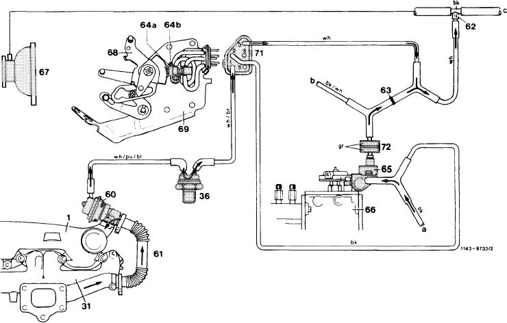
Vacuum routing after eliminating free travel
1 Intake manifold
31 Exhaust manifold
36 Thermovalve 40 °C/104°F
60 Exhaust gas recirculation valve (EGR)
61 Corrugated tubing
62 Orifice
63 Orifice
64a Switchover valve, idle speed shutoff — EGR 64b Switchover valve, full throttle shutoff – EGR 65 Vacuum control valve
|
|
|||||||||||||||||||||||||||||||||||||||||||||||||||||||||||||||||||||
|
|
||||||||||||||||||||||||||||||||||||||||||||||||||||||||||||||||||||||
|
14.8-050/10 USA starting 1981 F3
|
||||||||||||||||||||||||||||||||||||||||||||||||||||||||||||||||||||||
|
|
||||||||||||||||||||||||||||||||||||||||||||||||||||||||||||||||||||||
|
|
|||||||||||||||||||||||||||||||||||||||||||||||||||||||||||||||||||||
|
At increasing load, the vacuum is gradually decreased via vacuum control valve (65). This also reduces the amount of recirculated exhaust gas. Shortly before reaching full load position, the switchover valve (64b) is vented to atmosphere via the cam of guide lever (68). The vacuum is completely removed, there will be no EGR.
|
|||||||||||||||||||||||||||||||||||||||||||||||||||||||||||||||||||||
|
|
|||||||||||||||||||||||||||||||||||||||||||||||||||||||||||||||||||||
 |
|||||||||||||||||||||||||||||||||||||||||||||||||||||||||||||||||||||
|
|
|||||||||||||||||||||||||||||||||||||||||||||||||||||||||||||||||||||
|
Venting process when actuating full throttle shutoff
1 Intake manifold
31 Exhaust manifold
36 Thermovalve 40 °C/104 °F
60 Exhaust gas recirculation valve (EGR)
61 Corrugated tubing
62 Orifice
63 Orifice
64a Switchover valve, idle speed shutoff — EGR 64b Switchover valve, full throttle shutoff – EGR 65 Vacuum control valve
|
|
||||||||||||||||||||||||||||||||||||||||||||||||||||||||||||||||||||
|
|
|||||||||||||||||||||||||||||||||||||||||||||||||||||||||||||||||||||
|
14.8-050/11 USA starting 1981 F3
|
|||||||||||||||||||||||||||||||||||||||||||||||||||||||||||||||||||||
|
|
|||||||||||||||||||||||||||||||||||||||||||||||||||||||||||||||||||||
|
|
|||
|
E. Components with operation
model year 1984 California
|
 |
||
|
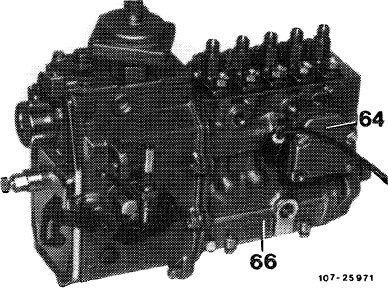
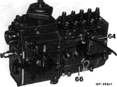
Injection pump
The emission control system requires a control rod travel indicator. The indicator is attached to pump housing inside in range of control rod.
|
|||
|
64 Control rod travel indicator 66 Injection pump
|
|||
|
|
|||
|
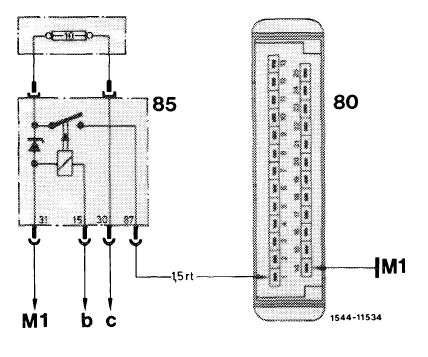
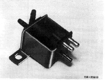
Overvoltage protection
Located in fusebox on model 126 and behind glove box on model 123. Serves to protect the electronic control unit. Fuse 10 A is installed at top of over-voltage protection.
|
 |
||
|
Layout model 1 23
|
|||
|
|
|||
|
When the ignition is switched on, terminal 15 is energized. The relay attracts and the control unit is provided with battery voltage.
|
 |
||
|
80 Control unit
85 Overvoltage protection
M1 Main ground behind instrument cluster
b Fuse capsule terminal 15
c Supporting lug terminal 30
|
|||
|
|
|||
|
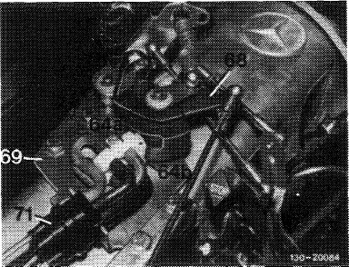
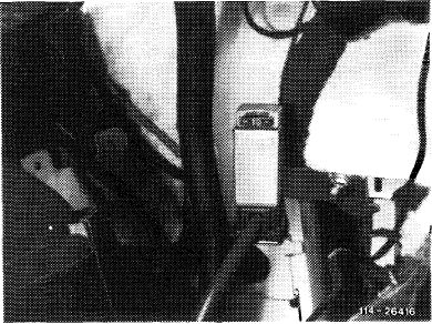
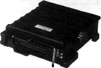
Electronic control unit
Attached in legroom at the right behind side panelling.
Control unit is connected to battery voltage after ignition has been switched on.
|
 |
||
|
|
|||
|
114-25969
|
|||
|
|
|||
|
14.8-050/12 USA 1984 California F 3
|
|||
|
|
|||
|
|
|||
|
The following signals are put in:
• Coolant temperature
• Engine rpm
• Control rod travel
• Barometric pressure
The inside of the control unit is provided with bellows (for altitude corrections).
The input signals are processed and the pressure converter (84) or the switchover valve (81) are pertinently activated.
|
|||
|
|
|||
|
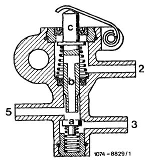
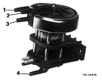
Pressure converter
The vacuum generated by the vacuum pump of the engine is converted into a load-dependent vacuum signal by the pressure converter. The signal serves for controlling the EGR-valve.
|
 |
||
|
1 EGR-valve connection
2 Vacuum pump connection
3 Positive vent line
4 Positive vent line
|
|||
|
|
|||
|
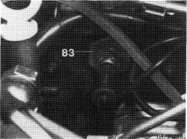
Temperature sensor coolant (NTC)
The coolant temperature is obtained by a temperature sensor (83), which is installed on lefthand side of cylinder head. The resistance of the temperature sensor changes in dependence of the coolant temperature.
|
 |
||
|
|
|||
|
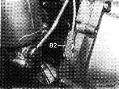
Rpm sensor
An inductance indicator which is screwed in on intermediate flange to automatic transmission (arrow).
The indicator comprises a magnetic core and a coil. It will pick up the engine speed for transmission to control unit in the shape of an AC voltage.
|
 |
||
|
|
|||
|
14.8-050/13 USA 1984 California F3
|
|||
|
|
|||
|
|
||||
|
Control rod travel indicator
The control rod travel indicator is attached to pump housing at the right at level of control rod.
|
 |
|||
|
64 Control rod travel indicator 66 Injection pump
|
||||
|
|
||||
|
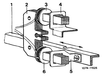
Layout
The control rod travel indicator comprises an iron core, two coils (measuring and fixed value coil) and two short circuit rings. It is connected to the electronic control unit by means of a 3-pole plug.
Coils (3) and (6) are attached to an iron core (2) fixed in housing. The short circuit ring (5) is connected to control rod (1) and slides this control rod free of contact on lower leg of iron core. The fixed value coil (3) and the short circuit ring (4) are attached to upper leg.
|
||||
|
|
||||
|
1 Control rod 4
2 Iron core 5
3 Fixed value coil 6
|
Bypass ring (fixed)
Short circuit ring (movable)
Measuring coil
|
 |
||
|
|
||||
|
Operation
Together with short circuit ring (4) the fixed value coil (3) provides a constant inductance.
The distance between short circuit ring (5) and measuring coil (6) is changed depending on change of location of control rod (1). The resulting variable inductance is compared with the constant. From these data, the electronic control unit determines the control travel.
|
||||
|
|
||||
|
14.8-050/14 USA 1984 California F 3
|
||||
|
|
||||
|
|
|||
|
Switchover valve (electric)
This valve is activated depending on load condition of engine by way of control unit and provides the vacuum for the circulating air safety valve.
|
 |
||
|
Layout modeM 23
|
|||
|
|
|||
|
Circulating air safety valve
Integrated on compressor housing of exhaust gas turbocharger. The EGR quantity is increased in partial load range by partial reduction of boost pressure.
When the circulating air safety valve is activated with a vacuum, the valve will open and will let a part of the boost air in front of compressor flow back in a bypass system.
|
|||
|
|
|||
|
14.8-050/15 USA 1984 California F 3
|
|||
|
|
|||
|
|
|||
|
F. Total operation <@> model year 1984 California
EGR proceeds after the following points have been met:
• Coolant temperature > 40 °C and < 90 °C.
• Engine speed > 500/min.
• Load signal of injection pump:
Idle speed auxiliary units switched off. Selector lever in position „P” or „N”.
Partial load auxiliary units switched on and selector lever in driving position.
The resistance of the coolant temperature sensor changes in dependence of the coolant temperature and thereby provides the input signal for the EGR electronic control system.
|
|||
|
|
|||
|
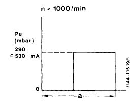
Engine speed > 500/min < 1000/min
In this rpm range (without load) the pressure converter (84) is activated with approx. 530 mA. The result is a vacuum at EGR-valve of approx. 290 mbar. The valve opens completely; max. possible EGR will result.
By engaging a driving position and switching on auxiliary units, a given load signal will be exceeded. The pressure converter will be deenergized and the vacuum toward EGR valve will be exhausted. There will be no more EGR.
|
|||
|
|
|||
|
a Load signal injection pump
|
 |
||
|
|
|||
|
14.8-050/16 USA 1984 California F 3
|
|||
|
|
|||
|
|
|||
|
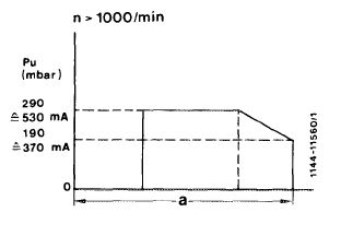
Engine speed > 1000/min
At engine speeds > 1000/min the pressure converter is also activated with approx. 530 mA in partial load range. Max. possible EGR will result.
With increasing load the current is reduced to 370 mA and the pressure converter will be deenergized as from a given load signal. In parallel with the reducing current the vacuum on EGR-valve will be exhausted and the EGR quantity will be reduced.
At 370 mA the vacuum on EGR-valve amounts to 190 mbar. This is the closing point of the EGR-valve; there will be no more EGR.
|
|||
|
|
|||
|
a Load signal injection pump
|
 |
||
|
|
|||
|
In addition, the circulating air safety valve will be completely opened at an engine speed > 1000/min and the respective load signal of the circulating air safety valve.
With increasing altitude a bellows integrated in control unit serves to reduce the EGR quantity in accordance with the prevailing air pressure.
|
|||
|
|
|||
|
14.8-050/17 USA 1984 California F3
|
|||
|
|
|||