Removal and installation of injection timing device
|
|
||||||||||||||||||||||||||||||||||||||
|
07.1—240 Removal and installation of injection timing device
|
||||||||||||||||||||||||||||||||||||||
|
|
||||||||||||||||||||||||||||||||||||||
|
Job no. of flat rates or standard texts and flat rates data 07—8014.
|
||||||||||||||||||||||||||||||||||||||
|
|
||||||||||||||||||||||||||||||||||||||
|
||||||||||||||||||||||||||||||||||||||
|
|
||||||||||||||||||||||||||||||||||||||
|
Impact extractor for guide rail pins (basic unit)
|
 |
116 589 20 33 00
|
||||||||||||||||||||||||||||||||||||
|
|
||||||||||||||||||||||||||||||||||||||
|
||||||||||||||||||||||||||||||||||||||
|
|
||||||||||||||||||||||||||||||||||||||
|
Supporting plate
|
 |
616 589 02 40 00
|
||||||||||||||||||||||||||||||||||||
|
|
||||||||||||||||||||||||||||||||||||||
|
Note
|
||||||||||||||||||||||||||||||||||||||
|
|
||||||||||||||||||||||||||||||||||||||
|
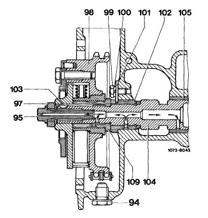
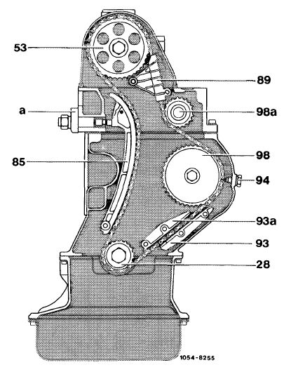
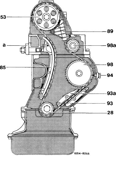
The injection timing device is attached to the intermediate sprocket shaft (104) by a hex-head bolt (95).
Vacuum pump lubrication is provided via the intermediate sprocket shaft (104) and the hollow hex-head bolt (95). The adjustment range of the injection timing device amounts to 8° up to model year 1979, starting model year 1980 7.5°.
|
 |
|||||||||||||||||||||||||||||||||||||
|
94 Retaining screw
95 Hex-head bolt M 10×45
97 Washer
98 Injection timing device
99 BoltM6x 12
100 Lock washer B 6
101 Lock washer
|
102 Bearing bush
103 Woodruff key
104 Intermediate sprocket shaft
105 Bearing bush, rear 109 Bearing bush, injection
timing device
|
|||||||||||||||||||||||||||||||||||||
|
|
||||||||||||||||||||||||||||||||||||||
|
07.1.8-240/1 F3
|
||||||||||||||||||||||||||||||||||||||
|
|
||||||||||||||||||||||||||||||||||||||
|
|
|||||
|
Removal
|
 |
||||
|
1
|
Remove radiator.
|
||||
|
2 Unscrew suction and pressure line of diaphragm vacuum pump or suction line of piston vacuum pump and vacuum pump from cylinder crankcase.
3 Unscrew fastening nut of injection timing device.
4 Remove cylinder head cover.
5 Unscrew bolt holding camshaft sprocket (53).
|
|||||
|
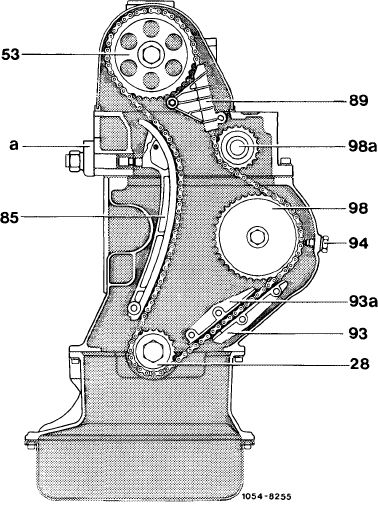
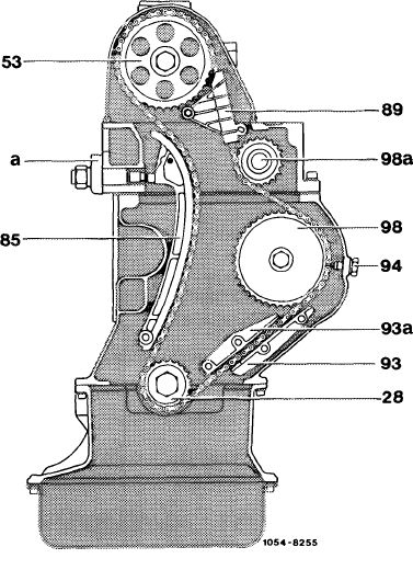
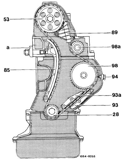
53 Camshaft sprocket
89 Guide rail
94 Retaining screw
|
93 Guide rail 93a Guide rail
|
||||
|
|
|||||
|
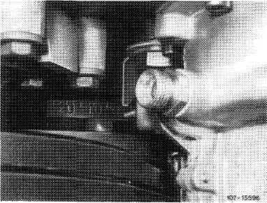
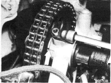
6 Turn crankshaft in normal direction to TDC mark.
|
 |
||||
|
|
|||||
|
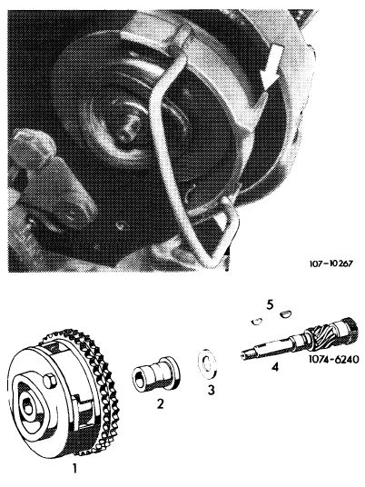
For correct camshaft alignment, position mark on shim adjacent to that on 1st camshaft bearing (arrow).
|
 |
||||
|
|
|||||
|
07.1.8-240/2 F3
|
|||||
|
|
|||||
|
|
|||||
|
7 Using ink or paint, mark meshing point of chain on injection timing device, and position of injection timing device relative to crankcase.
8 Remove chain tensioner (05—310).
9 Unscrew hex-head bolts, withdraw bearing pin and then remove guide rail (89).
10 Detach camshaft sprocket, noting shim between camshaft and camshaft sprocket. Leave chain on sprocket and deposit together in chain box.
|
 |
||||
|
11 Unscrew chain drive retaining screw (94) and withdraw upper pin of guide rail (93) using puller.
|
|||||
|
53 Camshaft sprocket 89 Guide rail
|
93 Guide rail 93a Guide rail
94 Retaining screw
|
||||
|
|
|||||
|
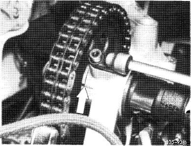
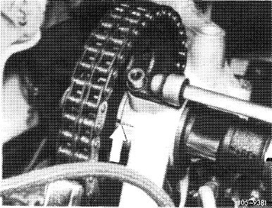
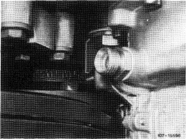
12 Lift chain out of injection timing device, sliding support plate between injection timing device and chain for this purpose. For better fixing, introduce guide pin (arrow) into tapped hole.
13 Remove or push off injection timing device.
Attention:
After removing injection timing device, be sure not to turn crankshaft or camshaft.
|
 |
||||
|
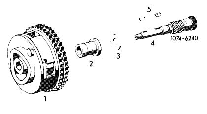
14 Remove injection timing device bush (2) and thrust ring (3) from intermediate sprocket shaft.
|
|||||
|
1 Injection timing device
2 Bush
3 Thrust ring
|
4 Intermediate sprocket shaft
5 Woodruff keys
|
||||
|
|
|||||
|
07.1.8-240/3 F3
|
|||||
|
|
|||||
|
|
|||
|
15 Check guide rails (93 and 93a) (sight-check), exchanging if necessary.
|
|||
|
|
|||
|
Installation
|
 |
||
|
16 Oil thrust ring (3) and bush (2), slipping onto intermediate sprocket shaft. Make sure that both Woodruff keys (5) are correctly seated (illustration. No. 14).
Note: If injection timing device needs exchanging, position the old one on the new one in such a way that the keyways of the one agree with those of the other. The paint mark on the old injection timing device must now be transferred to the new one.
17 Slip injection timing device onto intermediate sprocket shaft.
|
|||
|
93 Guide rail 93a Guide rail
|
|||
|
|
|||
|
18 Draw chain upward and lift camshaft sprocket with chain, making sure that mark on injection timing device agrees with that on crankcase. If necessary, turn injection timing device until the two marks agree again. Then withdraw supporting plate. If marks are offset, insert supporting plate again and relocate chain on sprocket to make marks agree.
|
|||
|
|
|||
|
19 Slip camshaft sprocket and chain onto camshaft, making sure that mark in shim agrees with mark in first camshaft bearing.
|
 |
||
|
|
|||
|
07.1.8-240/4 F3
|
|||
|
|
|||
|
|
|||
|
Check once again whether all marks are aligned in same way as before removal and whether TDC position of balance disk is correct.
|
 |
||
|
|
|||
 |
|||
|
|
|||
|
20 Install chain tensioner (05-310).
21 Introduce bearing pin of guide rail (93a) into crankcase, coating pin end with sealant. While driving into position, make sure that wire retainer of guide rail engages notch in bearing pin.
|
 |
||
|
22 Insert and tighten retaining screw (94) with new sealing ring.
23 Check start of delivery adjusting if necessary (07.1-110and 115).
24 Vent injection system (07.1-140).
|
|||
|
|
|||
|
07.1.8-240/5
|
|||
|
|
|||
|
|
|||
|
25 Fit hollow hex-head bolt and torque to 40 Nm.
Attention:
Be sure to use hollow hex-head bolt only.
|
|||
|
|
|||
|
26 Check end play of intermediate sprocket shaft Specified value is 0.05—0.12 mm. Withdraw thrust ring (3) if necessary.
|
 |
||
|
|
|||
|
27 Insert camshaft sprocket bolt and torque to 80 Nm.
28 Check injection timing device for satisfactory operation, using a wrench to turn hexagon screw clockwise to stop. When screw is released, injection timing device must return to old position.
29 Fit vacuum pump with new gasket and connect vacuum lines.
30 Hold guide rail (89) in position, insert drive pin and tighten.
31 Fit cylinder head cover, making sure that rubber gasket is correctly seated.
32 Attach and check control linkage, adjusting if necessary (30-300).
33 Fit radiator and connect all lines.
34 Run engine and check for leakage.
|
 |
||
|
|
|||
|
07.1.8-240/6 F2
|
|||
|
|
|||