Operation of preglow system
|
|
|||
|
15—705 Operation of preglow system
|
|||
|
|
|||
|
A. General information
|
|||
|
|
|||
|
On a diesel engine, combustion is effected by self-ignition of the fuel sprayed into the highly compressed and thereby highly heated combustion air.
In the cold engine, the self-ignition temperature is not attained by compression alone. A preglow system is therefore required, which serves the purpose of increasing the temperature of the compressed air to facilitate the firing of the cold engine by the ignition of fuel particles on filament of glow plug.
The duration of preglowing depends on temperature of engine and on ambient temperature.
|
|||
|
|
|||
|
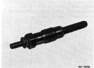
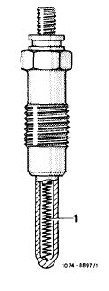
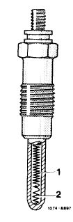
Design of pencil element glow plugs
Pencil element glow plugs consist essentially of a housing with M 12 x 1.25 screw-in threads and a pencil element pressed into housing.
|
 |
||
|
|
|||
|
The single-pole connecting pin is glued to housing by means of a non-releasable round aluminum nut.
The pencil element glow plugs are designed for a current of 11 volts and are operated in parallel.
|
|||
|
|
|||
|
15.8-705/1 F3
|
|||
|
|
|||
|
|
|||
|
The pencil element is heated indirectly by means of a heater element. This heater element, a coil made of a resistance wire, is embedded and insulated in a ceramic compound.
|
 |
||
|
|
|||
|
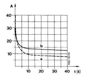
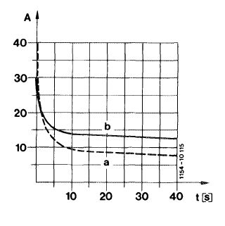
When the glow system is switched on, each glow plug is subject to a current of approx. 20 amps (peak impulse of approx. 40 amps).
Under the influence of increasing heat, the inherent resistance of the glow plug increases and will limit the current to approx. 8 amps.
|
 |
||
|
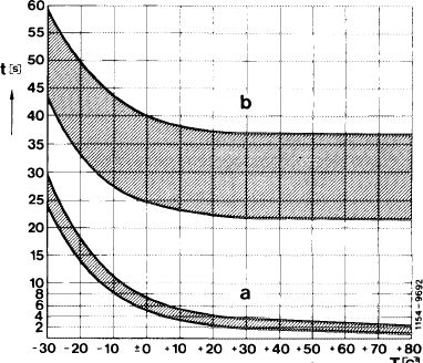
a Current curve of pencil element glow plug
|
|||
|
|
|||
|
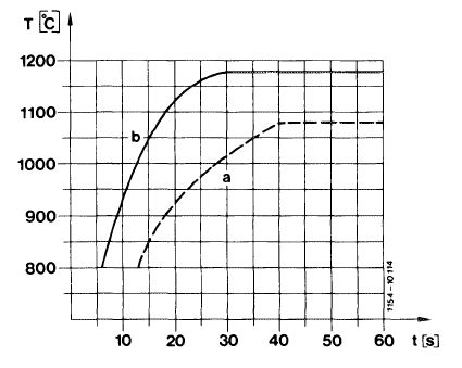
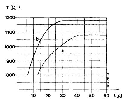
After a glow period of approx. 20 seconds a heater pencil element temperature of 900 °C/1652 °F will be attained, after approx. 50 seconds the max. temperature will be 1080 °C/1976 °F.
|
 |
||
|
a Temperature curve of pencil element glow plug
|
|||
|
|
|||
|
15.8-705/2 F3
|
|||
|
|
|||
|
|
|||
|
Design of quick-start pencil element glow plugs
|
 |
||
|
Except for heater element, the design of a quick-start pencil element glow plug is the same as that of a pencil element glow plug.
As an external identification, the connecting pin is screwed to the housing by means of a non-releasable round brass nut.
The heater element consists of a heater and control coil connected in series.
|
|||
|
|
|||
|
When the glow system is switched on, each glow plug will be subject to a current of approx. 30 amps.
The glow plug is heated very quickly by heater coil. With increasing temperature, the control coil increases its resistance and limits the current toapprox. 8—15 amps. This will protect the glow plug against overloads.
|
 |
||
|
b Current curve of quick-start pencil element glow plug
|
|||
|
|
|||
|
After a glow period of 9 seconds a pencil element temperature of approx. 900 °C/1652 °F is attained, after 30 seconds the max. temperature amounts to 1180°C/1976°F.
|
 |
||
|
b Temperature curve of quick-start pencil element glow plug
|
|||
|
|
|||
|
15.8-705/3 F 3
|
|||
|
|
|||
|
|
|||
|
B. Preglow system engine 617.950 @)1978-1980
|
|||
|
|
|||
|
General information
|
|||
|
|
|||
|
The essential components of the preglow system are the pencil element glow plugs, model year 1980quick-start pencil element glow plugs, preglow time relay, temperature sensor and preglow indicator lamp.
|
|||
|
|
|||
 |
|||
|
|
|||
|
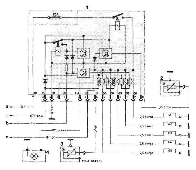
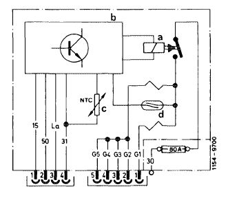
Wiring diagram
1 Preglow time relay
2 Temperature sensor preglow system
3 Temperature sensor coolant
4 Preglow indicator lamp
|
G 1 — G 5 Pencil element glow plugs
a Cable connector engine harness terminal 30
b Relay air conditioning/starter terminal 50
c Plug instrument cluster jack 3
|
||
|
|
|||
|
15.8-705/4 F 3
|
|||
|
|
|||
|
|
|||
|
The pencil element glow plugs are designed for a current of 11 volts and connected in parallel. For this reason, preglowing will proceed even if one pencil element glow plug fails.
|
|||
|
|
|||
|
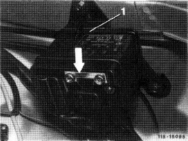
Preglow time relay
|
 |
||
|
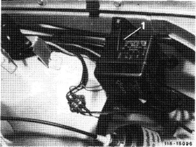
The preglow time relay is located in engine compartment at left of wheel house.
|
|||
|
|
|||
|
Upon removal of clipped-on cap on preglow time relay the 80-amps fuse and the electric connections will be accessible.
|
 |
||
|
|
|||
|
Functions of preglow time relay
|
|||
|
|
|||
|
The preglow time relay has the following functions:
— Switching of glow current
— Ready-to-start indicator
— Safety shutoff
— Fault indicator
|
|||
|
|
|||
|
15.8-705/5 F3
|
|||
|
|
|||
|
|
|||
|
Switching of glow current
|
|||
|
|
|||
|
When the preglow system is switched on in key position „2” (preglowing, driving) the preglow time relay is activated by terminal 15 of starter switch.
|
|||
|
|
|||
|
The power relay in preglow time relay closes the circuit of terminal 30 (battery +) via 80-amps fuse to pencil element glow plugs.
|
|||
|
|
|||
|
When the key is turned into position „3” (start) the power relay — activated by terminal 50 — remains in energized condition. The glow process continues until the key is turned to position „2”.
|
|||
|
|
|||
|
Ready-to-start indicator
|
 |
||
|
A temperature sensor installed in coolant circuit determines the glow period in preglow time relay.
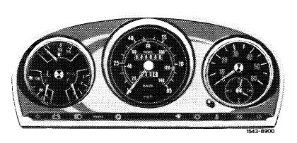
When the glow system is switched on, the preglow indicator lamp in instrument cluster lights up.
|
|||
|
|
|||
|
15.8-705/6 F 3
|
|||
|
|
|||
|
|
|||
|
As soon as the required glow period, depending on coolant temperature, is attained, the preglow indicator lamp goes out and thereby indicates ready-to-start condition.
|
 |
||
|
|
|||
|
Safety shutoff
|
|||
|
|
|||
|
If there is no start following indication of ready-to-start condition, the glow current is interrupted by the safety shutoff, after 90 + 20 seconds for model year 1978/1979, after 50+10 seconds for model year 1980.
|
|||
|
|
|||
|
For subsequent starting, the glow system is again switched on via terminal 50 for the duration of the starting procedure.
|
|||
|
|
|||
|
Fault indicator
|
|||
|
|
|||
|
A functional fault of the preglow system is indicated by the preglow indicator lamp during or after the pre-glowing has been completed.
The preglow indicator lamp is controlled by the electronic system in preglow time relay.
|
|||
|
|
|||
|
15.8-705/7 F3
|
|||
|
|
|||
|
|
|||
|
If the glow current circuit is interrupted, e.g. by a defective 80-amps fuse or power relay in preglow time relay, the electronic system receives no current from terminal 30 and the preglow indicator lamp will flash for approx. 30 seconds after the preglow system has been switched on.
If one or several pencil element glow plugs or lines are interrupted, the preglow indicator lamp will flash for approx. 30 seconds after starting.
|
 |
||
|
|
|||
|
For preglowing, the current flows through the Reed contact coils located in respective glow current circuits.
The resulting magnetic field will close the Reed contacts and a voltage from terminal 15 will be applied to electronic system.
|
|||
|
|
|||
|
If this voltage is interrupted, for example by a failing pencil element glow plug (the respective Reed contact remains open) the preglow indicator lamp will flash for approx. 30 seconds after starting.
|
|||
|
|
|||
|
15.8-705/8 F3
|
|||
|
|
|||
|
|
|||
|
C. Preglow system engine 617.95 standard version and (@) starting 1981
|
|||
|
|
|||
|
General information
|
|||
|
|
|||
|
The preglow system corresponds in principle to system of model year 1980.
The preglow time relay has been modified. In addition, the temperature sensor in coolant circuit is no longer installed.
|
|||
|
|
|||
 |
|||
|
|
|||
|
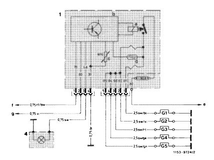
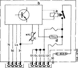
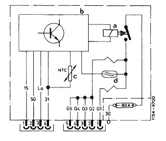
Wiring diagram
1 Preglow time relay
a Power relay
b Electronics
c Temperature sensor (NTC resistor)
d Reed relay
4 Preglow time relay
e To cable connector engine harness Terminal 30 in model 123 To point of support in fuse box Terminal 30 in model 126
|
f To fuse box terminal 15
g To plug connection starter lockout and backup lamp
switch terminal 50 G 1 — G 5 Pencil element glow plugs
|
||
|
|
|||
|
15.8-705/9 F3
|
|||
|
|
|||
|
|
|||
|
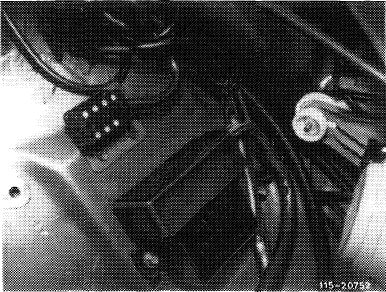
Preglow time relay
|
 |
||
|
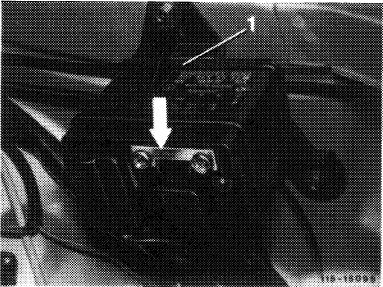
The preglow time relay is located in engine compartment at left on wheel house.
After removing plugged-on protective cap, the electrical connections as well as the fuse strip are accessible.
|
|||
|
Relay layout on engine 61 7.951
|
|||
|
|
|||
|
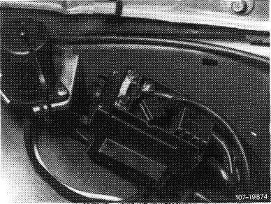
Relay layout on engine 61 7.952
|
 |
||
|
|
|||
|
The temperature sensor installed up to now in coolant circuit is no longer installed. Instead, the relay or relay ambient temperature is obtained by means of an NTC resistor in preglow time relay.
|
|||
|
|
|||
|
Functions of preglow time relay
|
|||
|
|
|||
|
The preglow time relay has the following functions:
— Switching of glow current
— Ready-to-start indicator
— Safety shutoff
— Fault indicator
|
|||
|
|
|||
|
15.8-705/10 F 3
|
|||
|
|
|||
|
|
|||
|
Switching of glow current
|
 |
||
|
When turning key into position „2” (preglowing, driving) the preglow time relay (current on terminal 15) is switched on. The power relay (a) closes the circuit of terminal 30 (plus) via fuse for pencil element glow plugs G1-G5.
|
|||
|
a Power relay
b Electronic unit
c Temperature sensor
(IMTC resistor) d Reed relay
|
|||
|
|
|||
|
When the key is moved into position „3” (start) the power relay (a) remains in energized condition under influence of terminal 50. Glowing continues until key is again turned into position „2”.
|
|||
|
|
|||
|
Ready-to-start indicator
|
|||
|
|
|||
|
A temperature sensor installed in preglow time relay determines the duration of the glow period.
When the glow system is switched on, the preglow indicator lamp in instrument cluster lights up.
|
|||
|
|
|||
|
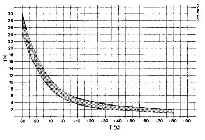
As soon as the required glow period, depending on ambient temperature of preglow time relay, has been attained, the preglow indicator lamp will go out and thereby indicate ready-to-start condition.
|
 |
||
|
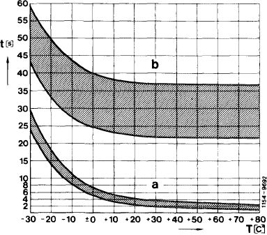
a Preglow period
|
|||
|
|
|||
|
15.8-705/11 F3
|
|||
|
|
|||
|
|
|||
|
Safety shutoff
|
|||
|
|
|||
|
If, upon indication of ready-to-start condition, there is no start within 20-35 seconds, the glow current is interrupted by the safety shutoff. For a subsequent start, the glow system is again switched on for the duration of the starting procedure.
|
|||
|
|
|||
|
The safety shutoff is no longer fixed, but is the result of the time up to ready-to-start condition (preglow indicator lamp goes out) plus 20 to 35 seconds.
|
 |
||
|
a Preglow period b Safety shutoff
|
|||
|
|
|||
|
Fault indicator
|
|||
|
|
|||
|
A fault in preglow system is indicated by the preglow indicator lamp not lighting up when key is actuated in position „2”.
|
|||
|
|
|||
|
The following faults are recognized:
— Interruption of line to connection terminal 30.
— Fuse 80 Amps, defective.
— Power relay in preglow time relay defective.
|
|||
|
|
|||
|
15.8-705/12 F3
|
|||
|
|
|||
|
|
|||
|
— Interruption of one or several lines to pencil element glow plugs.
— Interruption of one or several pencil element glow plugs.
|
|||
|
|
|||
|
Note: In the event of unfavorable tolerances of pencil element glow plugs or of Reed relay (d), response of fault indicator only after two pencil element glow plugs are defective is allowed.
|
|||
|
|
|||
|
Faults (monitoring of pencil element glow plugs) are indicated by comparing the current of the pencil element glow plug G 1 with current of remaining pencil element glow plugs G 2 to G 5 connected in parallel.
|
 |
||
|
a Power relay
b Electronic unit
c Temperature sensor
(NTC resistor) d Reed relay
|
|||
|
|
|||
|
The currents of the two lines to pencil element glow plugs G 1 and G 2 to G 5 are flowing through two oppositely oriented Reed relay windings having a different number of turns in windings.
|
|||
|
|
|||
|
15.8-705/13 F 3
|
|||
|
|
|||
|
|
|||
|
If the current flow in both windings is the same, the magnetic fields will cancel each other and the Reed contact will not respond.
|
|||
|
|
|||
|
If the balance of the magnetic fields is interrupted by the failure of one or several pencil element glow plugs, the Reed contact will close and the electronic unit (b) will be activated.
The preglow indicator lamp will switch off immediately and will therefore not light up when preglowing starts.
|
 |
||
|
a Power relay
b Electronic unit
c Temperature sensor
(NTC resistor) d Reed relay
|
|||
|
|
|||
|
15.8-705/14 F3
|
|||
|
|
|||