Installing preglow time relay with modified ventilation
|
|
|||
|
15—708 Installing preglow time relay with modified ventilation
|
|||
|
|
|||
|
Note
|
|||
|
|
|||
|
Since Septemb3r 1981 a preglow time relay with modified ventilation is installed for quick-start preglow system. The part number has not been changed.
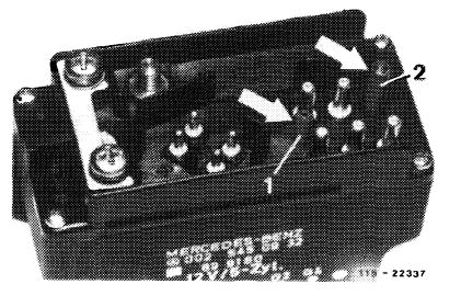
In the modified version of the preglow time relay, ventilation proceeds via coding pin (1). The coding pin (2) is also longer as before and the 5-pole coupler has been designed in such a manner that the ventilation is covered. In the former preglow time relay ventilation proceeded through a bore in housing.
|
 |
||
|
Modified preglow time relay
1 Ventilation
2 Higher coding pin
|
|||
|
|
|||
|
The modified preglow time relay can also be installed in vehicles prior to September 1981. In such a case, the modified 5-pole coupler must also be installed, since otherwise moisture may enter the relay.
Upon installation of the new relay, convert coupler of harness to new ventilation.
|
|||
|
|
|||
|
Layout of 5-pole coupler:
Jack 1 of coupler –
Pencil element glow plug cylinder 1—2.5 black/blue
Jack 2 of coupler =
Pencil element glow plug cylinder 2—2.5 black/purple
Jack 3 of coupler =
Pencil element glow plug cylinder 3—2.5 black/red
Jack 4 of coupler^
Pencil element glow plug cylinder 4—2.5 black/yellow
Jack 5 of coupler =
Pencil element glow plug cylinder 5—2.5 black/green
|
 |
||
|
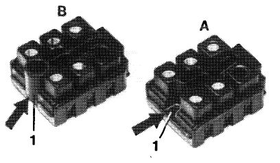
5-pole coupler
A 1st version B 2nd version
|
|||
|
115-22336
|
|||
|
|
|||
|
15.8-708/1 F3
|
|||
|
|
|||