Removal and installation of rocker arms with rocker arm bearing brackets
|
|
||||||||||||||||||||||||||||||||
|
05—235 Removal and installation of rocker arms with rocker arm bearing brackets
|
||||||||||||||||||||||||||||||||
|
|
||||||||||||||||||||||||||||||||
|
Valve clearance
|
with engine cold (approx. 20 °C)
|
with engine warm (60 °C ± 15 °C)
|
||||||||||||||||||||||||||||||
|
|
||||||||||||||||||||||||||||||||
|
Intake
|
0.101)
|
0.151)
|
||||||||||||||||||||||||||||||
|
|
||||||||||||||||||||||||||||||||
|
Exhaust
|
0.35
|
0.40
|
||||||||||||||||||||||||||||||
|
|
||||||||||||||||||||||||||||||||
|
0.05 mm higher during lasting outside temperatures below —20 °C.
|
||||||||||||||||||||||||||||||||
|
|
||||||||||||||||||||||||||||||||
|
||||||||||||||||||||||||||||||||
|
|
||||||||||||||||||||||||||||||||
|
Valve adjusting wrench 14 mm (2 each)
|
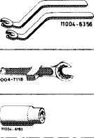 |
615 589 00 01 00
|
||||||||||||||||||||||||||||||
|
Holding wrench for valve spring retainer
|
615 589 00 03 00
|
|||||||||||||||||||||||||||||||
|
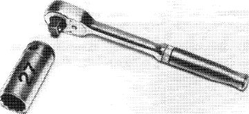
Socket 27 mm, 1/2″ square, for rotating engine
|
001 589 65 09 00
|
|||||||||||||||||||||||||||||||
|
|
||||||||||||||||||||||||||||||||
|
Contact handle for rotating engine (component of compression pressure recorder 001 589 46 21 00)
|
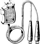 |
001 589 46 21 08
|
||||||||||||||||||||||||||||||
|
11OO4-8187
|
||||||||||||||||||||||||||||||||
|
|
||||||||||||||||||||||||||||||||
|
Note
|
||||||||||||||||||||||||||||||||
|
|
||||||||||||||||||||||||||||||||
|
Always install rocker arm at the same spot from where it has been removed.
If the rocker arms are renewed, also renew camshaft.
On rocker arms with carbide facing, renew damaged rocker arm only.
Removal
|
 |
|||||||||||||||||||||||||||||||
|
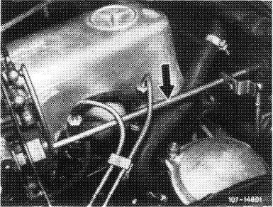
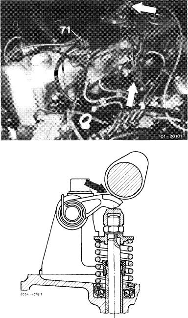
1 Disconnect regulating linkage to remove cylinder head cover. Pull out locking eye of longitudinal regulating shaft (arrow).
|
||||||||||||||||||||||||||||||||
|
Model 116.120
|
||||||||||||||||||||||||||||||||
|
|
||||||||||||||||||||||||||||||||
|
05.8-235/1 F 2
|
||||||||||||||||||||||||||||||||
|
|
||||||||||||||||||||||||||||||||
|
|
|||
|
On models 116.120 and 123, pull longitudinal regulating shaft out of rubber mount in forward direction and remove in rearward direction.
On model 126.120, pull longitudinal regulating shaft out of guide lever in rearward direction and remove in forward direction.
|
 |
||
|
Model 123
|
|||
|
|
|||
|
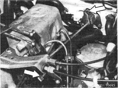
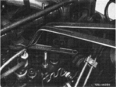
On models 123 with automatic transmission 722.303 (W 4 A 040) and 126.120, pull out central plug of vacuum lines (71) or vacuum lines. Disconnect Bowden wire, compress black plastic clip (arrow) and pull Bowden wire out of holder in rearward direction.
|
 |
||
|
Model 126.120
|
|||
|
2 Set camshaft in such a manner that the rocker arm is free of load. That is, the cam tips should point away from rocker arms.
For this purpose, rotate the crankshaft by means of the tool combination.
|
|||
|
|
|||
 |
|||
|
|
|||
|
05.8-235/2 F 2
|
|||
|
|
|||
|
|
|||
|
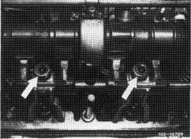
3 Screw out fastening screws of rocker arm bearing brackets (arrows).
|
 |
||
|
|
|||
|
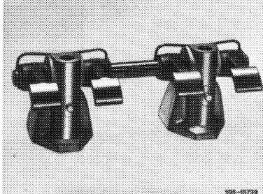
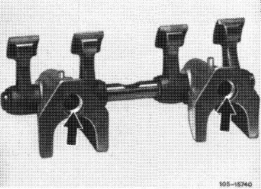
4 Completely remove rocker arm group in upward direction.
|
 |
||
|
Loosen stuck camshaft bearings by means of light blows with a plastic hammer.
|
|||
|
|
|||
|
Installation
|
|||
|
|
|||
|
5 Set complete rocker arm group and screw down.
Note: The rocker arm bearing brackets are located by means of fitted sleeves (arrows).
|
 |
||
|
|
|||
|
6 Adjust valve clearance (05—210).
|
 |
||
|
7 Mount cylinder head cover.
|
|||
|
|
|||
|
05.8-235/3 F 2
|
|||
|
|
|||