Removal and installation of pistons
|
|
|||||||||||||||||||||||||||||||||||||||||||
|
03—316 Removal and installation of pistons
|
|||||||||||||||||||||||||||||||||||||||||||
|
|
|||||||||||||||||||||||||||||||||||||||||||
|
Coordination piston-cylinder
|
|||||||||||||||||||||||||||||||||||||||||||
|
|
|||||||||||||||||||||||||||||||||||||||||||
|
Engine
|
Piston code number
|
Group no.
|
Standard dimension Std
Cylinder dia.
|
||||||||||||||||||||||||||||||||||||||||
|
Piston dia.
|
|||||||||||||||||||||||||||||||||||||||||||
|
|
|||||||||||||||||||||||||||||||||||||||||||
|
All
|
10.18
|
0 1 2
|
90.845 – 90.855 above 90.855 – 90.865 above 90.865-90.875
|
90.898 – 90.908 above 90.908-90.918 above 90.918-90.928
|
|||||||||||||||||||||||||||||||||||||||
|
|
|||||||||||||||||||||||||||||||||||||||||||
|
Piston standout
|
|||||||||||||||||||||||||||||||||||||||||||
|
|
|||||||||||||||||||||||||||||||||||||||||||
|
|||||||||||||||||||||||||||||||||||||||||||
|
|
|||||||||||||||||||||||||||||||||||||||||||
|
in bushing
|
0.018-0.029
|
||||||||||||||||||||||||||||||||||||||||||
|
|
|||||||||||||||||||||||||||||||||||||||||||
|
Piston pin clearance
|
|||||||||||||||||||||||||||||||||||||||||||
|
|
|||||||||||||||||||||||||||||||||||||||||||
|
in piston
|
0.00-0.01
|
||||||||||||||||||||||||||||||||||||||||||
|
|
|||||||||||||||||||||||||||||||||||||||||||
|
Gap clearance of piston rings
|
groove 1 groove 2 groove 3
|
0.20-0.40 0.15-0.35 0.20-0.45
|
1.5 1.0 1.0
|
||||||||||||||||||||||||||||||||||||||||
|
|
|||||||||||||||||||||||||||||||||||||||||||
|
Side clearance of piston rings
|
groove 1 groove 2 groove 3
|
0.110-0.142 0.070-0.112 0.030-0.062
|
0.20 0.15 0.1
|
||||||||||||||||||||||||||||||||||||||||
|
|
|||||||||||||||||||||||||||||||||||||||||||
|
Tightening torque
|
|||||||||||||||||||||||||||||||||||||||||||
|
|
|||||||||||||||||||||||||||||||||||||||||||
|
initial torque
|
40-50 Nm
|
||||||||||||||||||||||||||||||||||||||||||
|
|
|||||||||||||||||||||||||||||||||||||||||||
|
Connecting rod nuts
|
|||||||||||||||||||||||||||||||||||||||||||
|
|
|||||||||||||||||||||||||||||||||||||||||||
|
angle of rotation torque 90-100°
|
|||||||||||||||||||||||||||||||||||||||||||
|
|
|||||||||||||||||||||||||||||||||||||||||||
|
03.8-316/1 F2
|
|||||||||||||||||||||||||||||||||||||||||||
|
|
|||||||||||||||||||||||||||||||||||||||||||
|
|
|||||
|
Special tools
|
|||||
|
|
|||||
|
Expanding pliers for piston rings
|
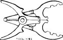 |
000 589 51 37 00
|
|||
|
|
|||||
|
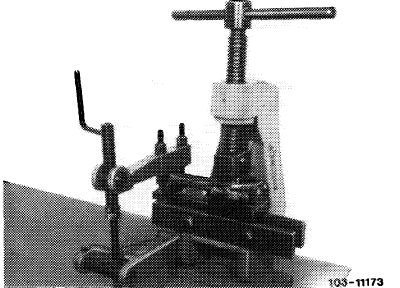
Clamping strap for piston rings
|
 |
000 589 04 14 00
|
|||
|
|
|||||
|
Angle of rotation tool
|
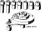 |
116 589 01 13 00
|
|||
|
|
|||||
|
Note
|
 |
||||
|
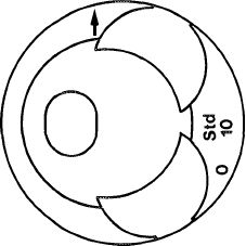
The group number 0, 1 or 2, the piston code number, e.g. 10 and the driving direction arrow are punched into piston crown.
The group number is also punched into cylinder crank-case parting surface.
Both group numbers (cylinder bore and piston) must be in agreement.
|
|||||
|
1034-8235
|
|||||
|
|
|||||
|
The specified piston clearance will then be maintained.
In the event of repairs, hone cylinder bores to dimensions of available piston plus piston clearance.
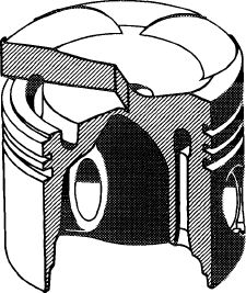
The piston shank is graphite-treated.
Due to the higher thermic load, the pistons are cooled by means of an annular duct located in piston crowns (functional description refer to 18—040).
|
 |
||||
|
|
|||||
|
1034-8120
|
|||||
|
|
|||||
|
03.8-316/2
|
|||||
|
|
|||||
|
|
|||
|
Removal
|
 |
||
|
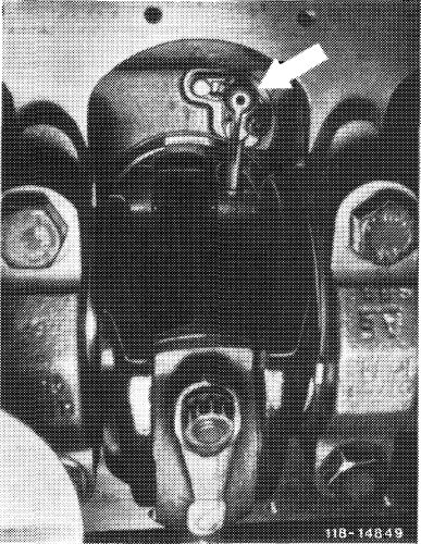
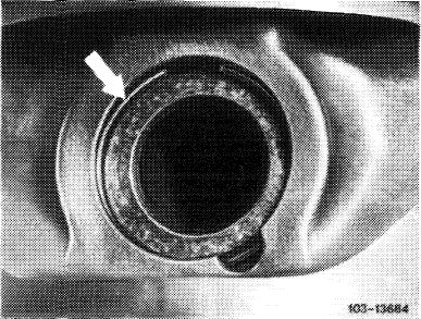
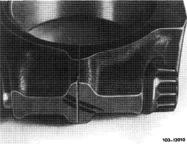
Attention!
To avoid damage to oil spray nozzles caused by contact with connecting rod during removal of piston, remove oil spray nozzles (arrow) first (18—040).
|
|||
|
|
|||
|
Removal
|
 |
||
|
1 Remove connecting rod with piston in upward direction.
|
|||
|
|
|||
|
2 Remove piston pin lock and force out piston pin.
|
 |
||
|
|
|||
|
03.8-316/3
|
|||
|
|
|||
|
|
|||
|
3 Recondition and square connecting rod (03—313).
|
 |
||
|
|
|||
|
Installation
|
 |
||
|
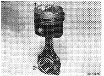
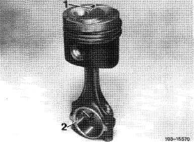
4 Place piston on connecting rod in such a manner that the arrow (1) is pointing in driving direction and the lock nuts (2) in connecting rod are pointing to lefthand engine side.
Attention!
Do not heat piston.
|
|||
|
|
|||
|
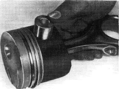
5 Push-in piston pin coated with engine oil manually.
|
 |
||
|
103-155?1
|
|||
|
|
|||
|
6 Place piston pin lock into groove. Check piston rings for easy operation.
When installing used pistons, check piston rings for gap and side clearance.
7 Lubricate clean cylinder bores, connecting rod bearing journals, connecting rod bearing shells and pistons.
|
 |
||
|
|
|||
|
03.8-316/4
|
|||
|
|
|||
|
|
|||
|
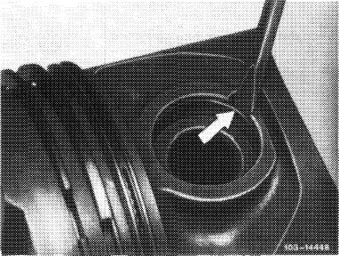
8 Distribute gaps of piston rings uniformly along circumference of piston.
9 Position piston ring clamping strap and insert piston.
The arrow in piston crown should point in driving direction.
|
 |
||
|
|
|||
|
10 Place connecting rod bearing cap with code numbers facing each other on connecting rod, lubricate connecting rod nuts, tighten to 40—50 Nm preload and 90—100°angle of rotation torque.
11 Rotate crankshaft and check clearance between piston pin eye and connecting rod.
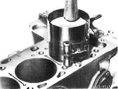
12 In TDC position of pistons, measure distance between piston crown and cylinder crankcase parting surface (refer to table).
|
 |
||
|
|
|||
|
13 Install oil spray nozzles (18-040).
|
|||
|
|
|||
|
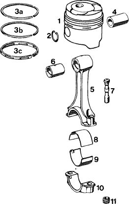
Piston and connecting rod
|
|||
|
|
|||
|
1 Piston
2 2 piston pin locks
3a Rectangular ring 3 mm
3b Rectangular ring 2 mm
3c Chamfered oil ring with expanding spring
4 Piston pin
5 Connecting rod
6 Connecting rod bushing
7 2 connecting rod bolts
8 Connecting rod bearing upper and lower half
10 Connecting rod bearing cap
11 2 connecting rod nuts
|
1033 7786/1
 |
||
|
|
|||
|
03.8-316/5 F2
|
|||
|
|
|||