Reconditioning and squaring connecting rod
|
|
||||
|
03—313 Reconditioning and squaring connecting rod
|
||||
|
|
||||
|
Data
|
||||
|
|
||||
|
Center of connecting rod bearing bore to center of connecting rod bushing bore
|
148.95 149.05
|
|||
|
|
||||
|
Width of connecting rod at connecting rod bearing bore
|
31.84 31.88
|
|||
|
|
||||
|
Width of connecting rod at connecting rod bushing bore
|
27.90 28.10
|
|||
|
|
||||
|
Basic bore for connecting rod bearing shells
|
55.60 55.62
|
|||
|
|
||||
|
standard dimension
|
31.000 31.025
|
|||
|
|
||||
|
Basic bore for connecting rod bushing
|
||||
|
|
||||
|
repair stage
|
31.500 31.525
|
|||
|
|
||||
|
standard dimension
|
31.060 31.100
|
|||
|
|
||||
|
Connecting rod bushing OD
|
||||
|
|
||||
|
repair stage
|
31.560 31.600
|
|||
|
|
||||
|
Connecting rod bushing ID
|
28.018 28.024
|
|||
|
|
||||
|
Roughness of connecting rod bushing, inside
|
0.004
|
|||
|
|
||||
|
Permissible offset of connecting rod bearing bore in relation to connecting rod bushing bore with reference to a length of 100 mm
|
0.1
|
|||
|
|
||||
|
Permissible deviation of parallel alignment of axes: Connecting rod bearing bore in relation to connecting rod bushing bore with reference to a length of 100 mm
|
0.045
|
|||
|
|
||||
|
Permissible difference in weight of complete connecting rods within one engine
|
5g
|
|||
|
|
||||
|
Tightening torque
|
||||
|
|
||||
|
initial torque
|
40-50 Nm
|
|||
|
|
||||
|
Connecting rod nuts
|
||||
|
|
||||
|
angle of rotation torque 90—100°
|
||||
|
|
||||
|
03.8-313/1 F 2
|
||||
|
|
||||
|
|
|||||
|
Special tool
|
|||||
|
|
|||||
|
Angle of rotation tool
|
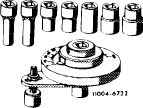 |
116 589 01 13 00
|
|||
|
|
|||||
|
Conventional tool
|
|||||
|
|
|||||
|
Connecting rod straightening tool
|
e.g. made by Hahn & Kolb, D-7000 Stuttgart model BC 503
|
||||
|
|
|||||
|
Note
|
 |
||||
|
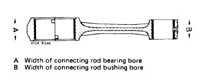
Connecting rod bearing bore (A) and connecting rod bushing bore (B) are of different width.
Do not install these connecting rods on the other diesel engines.
It is also not possible to install the connecting rods of the other diesel engines in this engine.
|
|||||
|
|
|||||
|
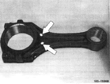
The connecting rods are subdivided into weight classes.
Colored dots on shank serve to identify the individual weight classes.
Install only connecting rods with the same color dots in engine.
|
 |
||||
|
|
|||||
|
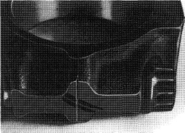
Connecting rods which are overheated as a result of bearing damage (blue discoloration) should no longer be used.
Connecting rod and connecting rod bearing cap are marked together. The connecting rod shank should have no transverse score marks and notches.
Connecting rods with machined connecting rod bushing are available as spare parts.
|
 |
||||
|
|
|||||
|
103-13910
|
|||||
|
|
|||||
|
03.8-313/2
|
|||||
|
|
|||||
|
|
|||||||||||||||||||||||||||||||||||||||||||||||||||
|
In the period from May to October 1980, connecting rod bearing shells of a second manufacturer (Karl Schmidt) were installed. Standard shells from Glyco.
Installation
|
|||||||||||||||||||||||||||||||||||||||||||||||||||
|
|
|||||||||||||||||||||||||||||||||||||||||||||||||||
|
|||||||||||||||||||||||||||||||||||||||||||||||||||
|
|
|||||||||||||||||||||||||||||||||||||||||||||||||||
|
Reconditioning
|
 |
||||||||||||||||||||||||||||||||||||||||||||||||||
|
1 Check connecting rod bolts and renew, if required (03-310).
|
|||||||||||||||||||||||||||||||||||||||||||||||||||
|
|
|||||||||||||||||||||||||||||||||||||||||||||||||||
|
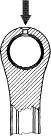
2 Check bores for connecting rod bolts.
Mount connecting rod bearing cap on a connecting rod bolt. If the connecting rod bearing cap is moving downwards under its own weight, the connecting rod must be replaced.
|
 |
||||||||||||||||||||||||||||||||||||||||||||||||||
|
|
|||||||||||||||||||||||||||||||||||||||||||||||||||
|
3 Mount connecting rod bearing caps, lubricate connecting rod nuts and tighten to 40—50 Nm preload and 90—100° angle of rotation torque.
4 Measure connecting rod bearing basic bore. If basic bore exceeds a specified value of 55.62 mm or is conical in shape, refinish bearing cap supporting surface on a face plate up to max. 0.02 mm.
|
 |
||||||||||||||||||||||||||||||||||||||||||||||||||
|
|
|||||||||||||||||||||||||||||||||||||||||||||||||||
|
03.8-313/3 F2
|
|||||||||||||||||||||||||||||||||||||||||||||||||||
|
|
|||||||||||||||||||||||||||||||||||||||||||||||||||
|
|
||||
|
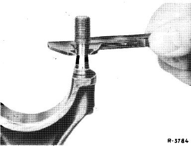
5 Press-in new connecting rod bushing in such a manner that the oil bores are in alignment.
Pressing-in pressure 2500 N.
6 Machine or ream connecting rod bushing.
7 Refinish lateral contact surfaces of connecting rod on a face plate.
|
 |
1034-7788/1
|
||
|
|
||||
|
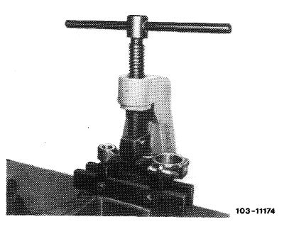
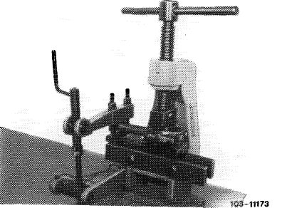
Squaring
|
 |
|||
|
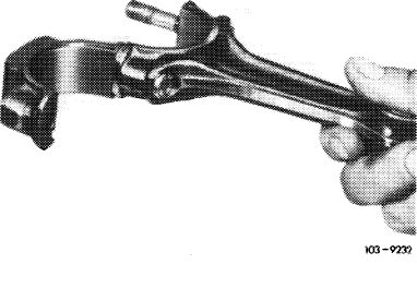
8 Square connecting rod by means of connecting rod tester.
9 Align connecting rod bearing bore in relation to connecting rod bushing bore (parallel alignment).
|
||||
|
|
||||
|
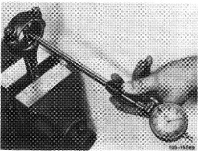
10 Check offset of connecting rod bearing bore in relation to connecting rod bushing bore and make corrections, if required.
|
 |
|||
|
|
||||
|
03.8-313/4 F2
|
||||
|
|
||||