Mounting of crankshaft
|
|
||||||||||||||||||||||||||||||||||||||||||||||||||||||||||||||||||
|
03-320 Mounting of crankshaft
|
||||||||||||||||||||||||||||||||||||||||||||||||||||||||||||||||||
|
|
||||||||||||||||||||||||||||||||||||||||||||||||||||||||||||||||||
|
Data
|
||||||||||||||||||||||||||||||||||||||||||||||||||||||||||||||||||
|
|
||||||||||||||||||||||||||||||||||||||||||||||||||||||||||||||||||
|
||||||||||||||||||||||||||||||||||||||||||||||||||||||||||||||||||
|
|
||||||||||||||||||||||||||||||||||||||||||||||||||||||||||||||||||
|
||||||||||||||||||||||||||||||||||||||||||||||||||||||||||||||||||
|
|
||||||||||||||||||||||||||||||||||||||||||||||||||||||||||||||||||
|
when new
|
0.031-0.0731)
|
|||||||||||||||||||||||||||||||||||||||||||||||||||||||||||||||||
|
|
||||||||||||||||||||||||||||||||||||||||||||||||||||||||||||||||||
|
Bearing play radial
|
||||||||||||||||||||||||||||||||||||||||||||||||||||||||||||||||||
|
|
||||||||||||||||||||||||||||||||||||||||||||||||||||||||||||||||||
|
wear limit
|
0.08
|
|||||||||||||||||||||||||||||||||||||||||||||||||||||||||||||||||
|
|
||||||||||||||||||||||||||||||||||||||||||||||||||||||||||||||||||
|
when new
|
0.10-0.25
|
0.12-0.26
|
||||||||||||||||||||||||||||||||||||||||||||||||||||||||||||||||
|
|
||||||||||||||||||||||||||||||||||||||||||||||||||||||||||||||||||
|
Bearing play axial
|
||||||||||||||||||||||||||||||||||||||||||||||||||||||||||||||||||
|
|
||||||||||||||||||||||||||||||||||||||||||||||||||||||||||||||||||
|
wear limit
|
0.30
|
0.50
|
||||||||||||||||||||||||||||||||||||||||||||||||||||||||||||||||
|
|
||||||||||||||||||||||||||||||||||||||||||||||||||||||||||||||||||
|
’) For radial play try for mean value.
|
||||||||||||||||||||||||||||||||||||||||||||||||||||||||||||||||||
|
|
||||||||||||||||||||||||||||||||||||||||||||||||||||||||||||||||||
|
03.8-320/1 F 2
|
||||||||||||||||||||||||||||||||||||||||||||||||||||||||||||||||||
|
|
||||||||||||||||||||||||||||||||||||||||||||||||||||||||||||||||||
|
|
||||||
|
Bearing shells
|
Wall thickness crankshaft bearing
|
Wall thickness connecting rod bearing
|
||||
|
|
||||||
|
Standard dimension
|
2.25
|
1.80
|
||||
|
|
||||||
|
1st repair stage 2nd repair stage 3rd repair stage 4th repair stage
|
2.37 2.50 2.62 2.75
|
1.92 2.05 2.17 2.30
|
||||
|
|
||||||
|
Tightening torques
|
Nm
|
|||||
|
|
||||||
|
Crankshaft bearing bolts
|
90
|
|||||
|
|
||||||
|
initial torque
|
40-50
|
|||||
|
|
||||||
|
Connecting rod nuts
|
||||||
|
|
||||||
|
angle of rotation torque 90—100°
|
||||||
|
|
||||||
|
Bolt M 18 x 1.5 x 45 on crankshaft
|
270-330
|
|||||
|
|
||||||
|
Necked-down screws for flywheel or driven plate
|
initial torque
|
30-40
|
||||
|
angle of rotation torque 90—100°
|
||||||
|
|
||||||
|
Special tools
|
||||||
|
|
||||||
|
Angle of rotation tool
|
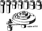 |
116 589 01 13 00
|
||||
|
|
||||||
|
Puller for balancing disc
|
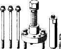 |
116 589 10 33 00
|
||||
|
|
||||||
|
Puller for crankshaft gear
|
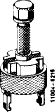 |
615 589 01 33 00
|
||||
|
|
||||||
|
Detent
|
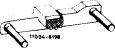 |
110 589 00 40 00
|
||||
|
|
||||||
|
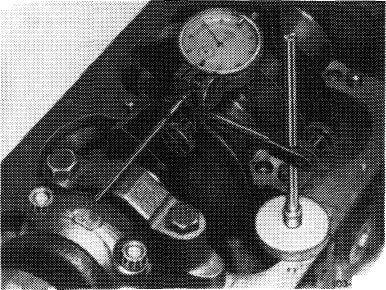
Dial gauge holder for measuring end play
|
 |
116 589 12 21 00
|
||||
|
|
||||||
|
03.8-320/2 F 2
|
||||||
|
|
||||||
|
|
||||
|
Note
|
||||
|
|
||||
|
Engine removed and disassembled.
Main oil ducts in crankcase open (also refer to 01-130).
Oil spray nozzles removed (18—040).
Oil ducts in cylinder crankcase and in crankshaft carefully cleaned.
|
||||
|
|
||||
|
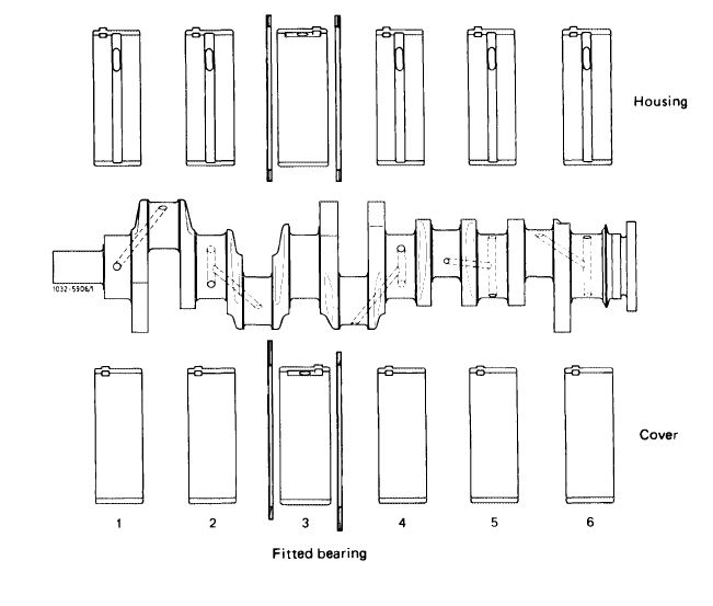
Check crankshaft for cracks, dimensional stability and concentricity (03-318).
For durability, the 3rd crankshaft bearing (fitted bearing) has been provided with standard bearing shells and thrust washers.
|
||||
|
|
||||
|
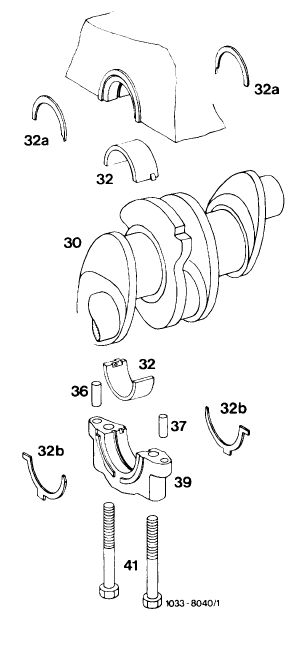
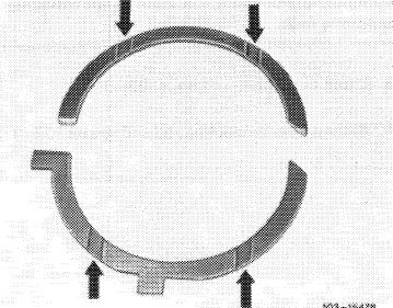
The thrust washers absorb the axial forces of the crankshaft.
The thrust washers (32a and 32b) inserted in cylinder crankcase and in bearing cap on both sides are similar in design.
As a protection against distorsion and to avoid assembly faults, the thrust washers in bearing cap are provided with two holding lugs each, with the lower lug placed out of center. In addition, all thrust washers are chamfered at one end.
|
 |
|||
|
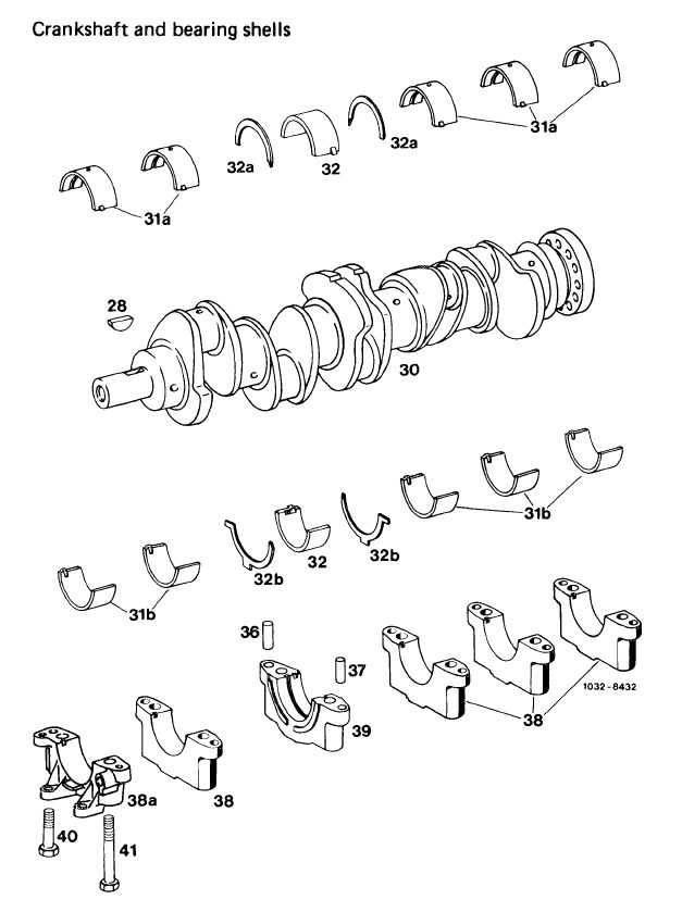
32 Bearing shells 32a Thrust washers in
cylinder crankcase 32b Thrust washers in
bearing cap
|
36 Cylindrical pin 10m 6 x 16
37 Cylindrical pin 8m 6×16 39 Bearing cap
41 Bolts M 12 x 75
|
|||
|
03.8-320/3 F 2
|
||||
|
|
||||
|
|
||
|
When reconditioning crankshafts, regrind width of fitted bearing journals to one of the dimensions named in table (section „Data”).
Coordinate thrust washers in accordance with pertinent journal widths (table).
Always install thrust washers of uniform thickness on both sides.
Regrinding of thrust washers is not permitted.
Spare part thrust washers are available in sets only. One set consists of an upper and a lower thrust washer (32a and 32b).
|
||
|
|
||
|
Thrust washer sets
Thickness in mm Set part no.
2.15 617 586 19 03
2.20 617 586 20 03
2.25 617 586 2109
2.35 617 586 22 03
2.40 617 586 3103
|
||
|
|
||
|
Due to the higher combustion pressures the fatigue strength of connecting rod bearing shells has been improved by changing the composition of the material.
On these engines, do not install connecting rod bearing shells of engine 617.912.
|
||
|
|
||
|
To improve bearing shell seat in cylinder crankcase on engine 617.950, the standout of the bearing shells has been increased from 0.000—0.030 mm to 0.030-0.060 mm. On engines 617.951/952, from start of series.
Installation
Engine Engine end no.
617.950 003 768
617.951 /952 Start of series
|
||
|
|
||
|
03.8-320/4 F 2
|
||
|
|
||
|
|
||||
|
Coordinating crankshaft bearings, installing crankshaft
|
 |
|||
|
1 Install crankshaft bearing cap. Pay attention to identification, 1 is at the front.
Do not interchange crankshaft bearing caps.
2 Tighten bolts to 90 Nm.
|
||||
|
|
||||
|
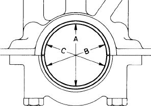
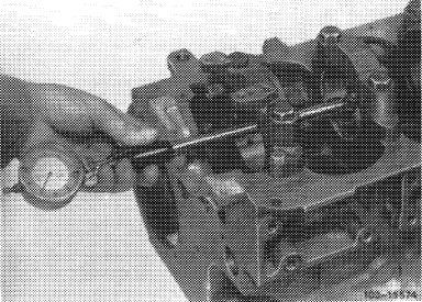
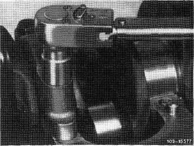
3 Measure basic bore in direction A, B and C on two levels (conicity).
If a basic bore exceeds the specified value or is conical, touch up bearing cap at its contact surface on a surface plate by max. 0.02 mm.
|
 |
Z-632
|
||
|
|
||||
|
4 Insert crankshaft bearing shells and mount bearing cap. Tighten bolts to 90 Nm.
|
 |
|||
|
|
||||
|
03.8-320/5 F 2
|
||||
|
|
||||
|
|
|||
 |
|||
|
|
|||
|
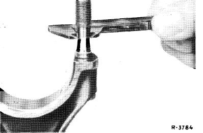
5 Measure bearing dia. and write down.
|
|||
|
|
|||
 |
|||
|
|
|||
|
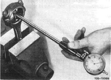
6 Measure crankshaft bearing journal, find crankshaft bearing radial play.
Note: The bearing play can be corrected by exchanging bearing shells, while trying for mean value of specified bearing play.
Crankshaft bearing shells without color coding are thicker than those with blue color coding, while taking into account that the wall thicknesses without color coding and those with color coding may overlap.
|
 |
||
|
03.8-320/6 F 2
|
|||
|
|
|||
|
|
|||
|
7 Measure width of fitted bearing journal and use pertinent thrust washers (refer to table, section „Data”).
|
 |
||
|
|
|||
|
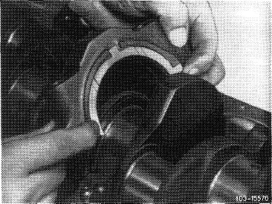
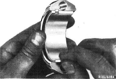
8 Renew rear crankshaft radial sealing ring (03—327).
9 Provide bearing shells, crankshaft and radial sealing ring with engine oil and insert crankshaft.
|
 |
||
|
|
|||
|
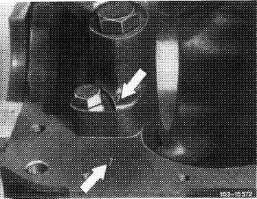
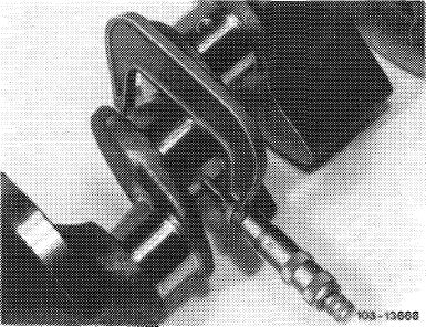
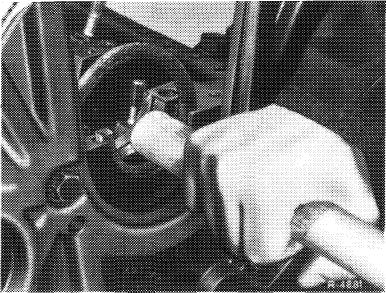
10 Provide thrust washers with engine oil and slip into grooves on fitted bearing (cylinder crankcase).
Attention!
The two oil grooves (arrows) in thrust washers should face crankshaft webs.
|
 |
||
|
|
|||
 |
|||
|
|
|||
|
03.8-320/7 F 2
|
|||
|
|
|||
|
|
|||
|
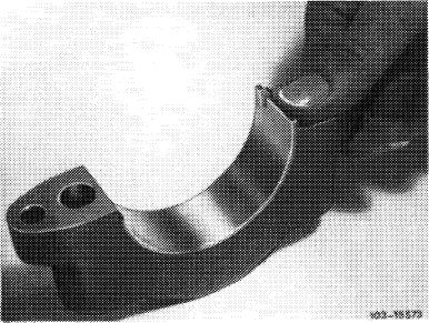
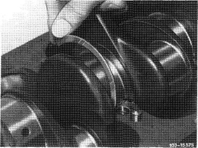
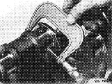
11 Mount fitted bearing cap.
Attention!
Provide thrust washers with engine oil and place into grooves on fitted bearing cap. The two oil grooves (arrows) in thrust washers should face crankshaft webs.
Hold both thrust washers in position and mount fitted bearing cap.
|
 |
||
|
|
|||
|
12 Mount crankshaft bearing cap.
|
 |
||
|
13 Tighten all bearing caps to 90 Nm.
|
|||
|
|
|||
|
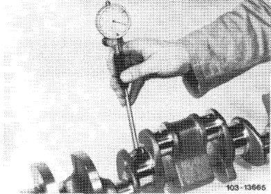
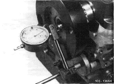
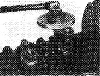
14 Measure crankshaft bearing end play.
15 Turn crankshaft manually and check for unobstructed running.
|
 |
||
|
|
|||
|
Coordinating connecting rod bearings and installing connecting rods
|
|||
|
|
|||
|
16 Check connecting rod bolts (03—310).
17 Recondition connecting rod and square (03—313).
|
 |
||
|
|
|||
|
03.8-320/8 F 2
|
|||
|
|
|||
|
|
|||
|
18 Mount connecting rod bearing cap, while paying attention to identification. Lubricate connecting rod nuts and tighten to 40—50 Nm.
19 Measure basic bore in two directions. On a basic bore which exceeds the specified value or is conical, touch up bearing cap at its contact surface on a surface plate by max. 0.02 mm.
|
 |
||
|
|
|||
|
20 Insert connecting rod bearing shells, mount connecting rod bearing cap with bearing shells and tighten connecting rod nuts to 40—50 Nm.
|
 |
||
|
|
|||
|
21 Measure bearing dia. and write down.
22 Measure connecting rod bearing journal, find connecting rod bearing radial play.
Note: The bearing play can be corrected by exchanging bearing shells, while trying for mean value of specified bearing play. Connecting rod bearing shells without color coding are thicker than those with blue color coding, while taking into account that the wall thicknesses without color coding and those with color coding may overlap.
|
 |
||
|
|
|||
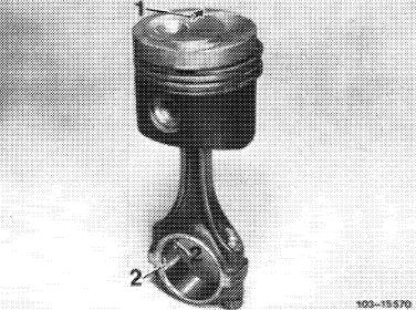
|
23 Mount piston on connecting rod (03—316).
24 Provide bearing shells, crankshaft, piston and cylinder walls with engine oil, install connecting rod with piston (03-316).
Pay attention to identification.
|
 |
||
|
|
|||
|
03.8-320/9 F 2
|
|||
|
|
|||
|
|
|||
|
25 Tighten connecting rod nuts to 40—50 Nm initial torque and 90—100° angle of rotation torque.
|
 |
||
|
|
|||
|
26 Measure connecting rod bearing end play. Check connecting rod for easy operation in piston.
Attention!
Disassemble and clean oil pump and renew, if required. Renew oil pressure relief valve, disassemble oil filter and clean. Carefully clean air-oil cooler. Clean oil spray nozzles (18—040).
Install initial operation oil filter element. Change engine oil and oil filter element after 1000-1500 km.
|
■15578
|
||
|
|
|||
|
03.8-320/10 F2
|
|||
|
|
|||
|
|
|||
 |
|||
|
|
|||
|
28 Woodruff key 36
30 Crankshaft 37
31a Bearing shells upper halves 38
31b Bearing shells lower halves 38a
32 Bearing shells (fitted bearing) 39
32a Thrust washers upper halves 40
32b Thrust washers lower halves 41
|
6 Cylinder pins 10m 6×16
6 Cylinder pins 8m 6×16
Camshaft bearing cap
Camshaft bearing cap no. 1
Camshaft bearing cap (fitted bearing)
Bolt M 8 x 25
12 bolts M 12×75
|
||
|
|
|||
|
03.8-320/11 F2
|
|||
|
|
|||