Adjusting injection timing (begin of delivery) (high pressure method) following checkup
|
|
|||||
|
07.1-115 Adjusting injection timing (begin of delivery) (high pressure method) following checkup
|
|||||
|
|
|||||
|
Job no. of flat rates or standard texts and flat rates data 07—8300.
|
|||||
|
|
|||||
|
Special tool
|
|||||
|
|
|||||
|
Socket element 13 mm, 3/8″ square
|
 |
000 589 21 07 22
|
|||
|
|
|||||
|
Preparation for checkup
|
|||||
|
|
|||||
|
Prior to adjustment, check begin of delivery (07.1-109 or 07.1-110).
|
|||||
|
|
|||||
|
A. Preparing for adjustment
|
 |
||||
|
1 Set crankshaft in direction of rotation to 24° + 1° before TDC in compression stroke of first cylinder.
2 Loosen fastening nuts on injection pump flange and nut or screw on supporting bracket.
|
|||||
|
|
|||||
|
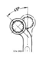
For loosening and tightening of fastening nuts or screws on supporting bracket, use self-bent box end wrench 13 mm.
|
 |
||||
|
|
|||||
|
07.1.8-115/1 F3
|
|||||
|
|
|||||
|
|
|||
|
B. Adjustment (high pressure method)
|
|||
|
|
|||
|
1 Unscrew all injection lines.
|
|||
|
|
|||
|
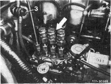
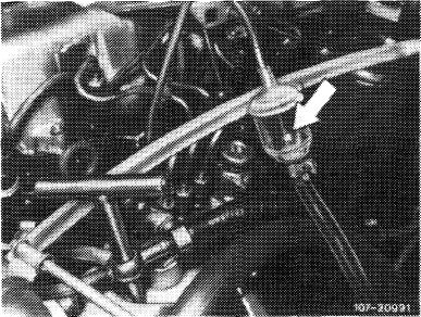
2 Screw pressure limiting valves (arrow) on pipe connections of injection pump.
The pressure limiting valves are required to protect the injection pump, e.g. when cranking with starter.
|
 |
||
|
|
|||
|
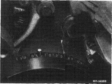
3 Switch on pump unit.
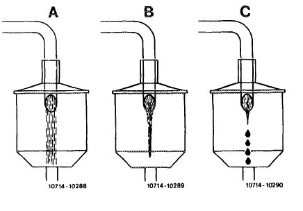
4 Swivel injection pump while watching fuel jet. Begin of delivery is attained, when the fuel jet changes into a formation of droplets (arrow).
|
 |
||
|
Nominal value: 24° + 1° before TDC.
|
|||
|
Swivel direction of injection pump
Toward engine = advances begin of delivery Away from engine = retards begin of delivery
Note: If possibilities for adjustment are insufficient, the injection pump must be changed over.
5 Check begin of delivery once again.
6 Shut off pump unit.
7 Assemble injection system.
8 Vent injection system (07.1 — 140). Run engine and check ail connections for leaks.
|
|||
 |
|||
|
A Fuel jet full
B Fuel jet constricted
prior to begin of delivery C Formation of droplets begin of delivery
|
|||
|
|
|||
|
07.1.8-115/2 F3
|
|||
|
|
|||
|
|
|||
|
C. Adjustment (low pressure method)
|
|||
|
|
|||
|
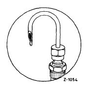
1 Swivel injection pump until fuel changes to droplets at overflow pipe. Formation of droplets: One droplet per second.
Attention!
While measuring, push regulating lever of injection pump to full load and pull vacuum hose from vacuum control unit.
|
 |
||
|
|
|||
|
Note: On pipe connections with relief orifice (2), no full fuel jet will come out of overflow pipe. However, measuring accuracy will not be impaired.
|
 |
||
|
Pipe connection MW-injection pump
|
|||
|
|
|||
|
Swivelling direction
toward engine = advances begin of delivery, away from engine = retards begin of delivery.
Note: Injection pump will have to be relocated if adjustment is inadequate (07.1—205).
|
|||
|
|
|||
|
2 Attach injection pump and recheck begin of delivery.
Install damper, adjust (07.1-200).
3 Attaeh injection pump.
4 Unscrew overflow pipe and pipe connection.
|
 |
||
|
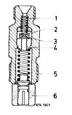
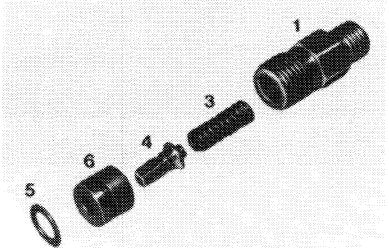
1 Pipe connection
3 Compression spring
4 Delivery valve
5 Copper sealing ring
6 Delivery valve holder
|
|||
|
|
|||
|
07.1.8-115/3 F3
|
|||
|
|
|||
|
|
||||
|
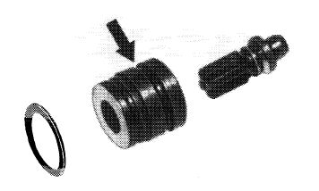
5 Fit pipe connection.
Remove delivery valve holder (6), checking whether delivery valve (4) moves freely in holder (6).
Insert delivery valve holder (6) with annular groove pointing downward.
Attention!
Starting with Bosch production date „249” (September 1982) the annular groove should point upwards.
The copper sealing ring is located beneath the delivery valve holder and need not be exchanged.
Smear thread of pipe connection (1) with oil, insert connection and torque to 40—50 Nm in one step.
6 Fit injection lines and vent injection system (07.1-140).
7 Check throttle linkage and adjust, if required (30-300).
8 Run engine and check all connections for leakage. Any pipe connection that is leaking has to be exchanged. In this case exchange copper sealing ring beneath delivery valve holder (07.1—210).
|
 |
|||
|
107-25354
|
||||
|
|
||||
|
07.1.8-115/4
|
F 3
|
|||
|
|
||||