Subsequent installation of separate check valve on fuel pump
|
|
|||
|
07.3—283 Subsequent installation of separate check valve on fuel pump
|
|||
|
|
|||
|
Note
|
|||
|
|
|||
|
In the event of a complaint concerning „Engine fires poorly when warm” an internal leak of fuel pump shows up, a check valve can be subsequently mounted to fuel pump.
|
|||
|
|
|||
|
Installation
|
 |
||
|
Fuel pump assembly with steel line between fuel pump and filter
1 Unscrew protective case.
2 Pinch fuel hoses (from fuel tank and to line toward engine) with one clamp each.
3 Unscrew fuel pump assembly on both front anti-vibration buffers.
|
|||
|
|
|||
|
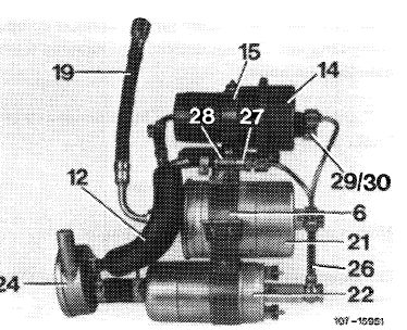
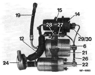
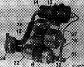
6 Holder for fuel pump and filter 12 Leak line 14 Pressure reservoir 1 5 Holder for pressure reservoir 19 Fuel hose
21 Filter
22 Fuel pump 24 Damper
26 Fuel pressure line
27 Pressure compensating valve
28 Clamp for pressure compensating valve
29 Closing cone
30 Coupling nut
31 Closing nut
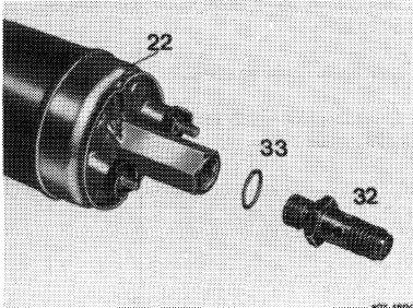
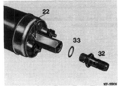
32 Check valve
33 Sealing ring
|
 |
||
|
|
|||
|
4 Unscrew steel line (26) on fuel pump, filter, reservoir and pressure compensating valve.
5 Screw check valve (32) with new copper sealing ring (33) to fuel pump.
|
 |
||
|
|
|||
|
07.3.2 Ila-283/1 F2
|
|||
|
|
|||
|
|
||||
|
6 Mount steel lines. For this purpose, slip fuel pump up to bead into holder. Connect steel line with new copper sealing rings and closing nut (screw-on closing nut only lightly). Hollow screw is no longer used.
Note: The plastic sheeting or plastic sleeve of pump and filter should project on holder of both sides. Be sure to replace if demaged. Remove pump and filter for this purpose.
7 Mount fuel filter in holder in such a manner that the steel line is in alignment with fuel pump.
|
 |
|||
|
|
||||
|
8 Mount steel line on reservoir and pressure compensating valve and tighten connections (applying counter-hold to check valve).
9 Tighten fuel pump and filter in holder and screw holder to anti-vibration buffers.
10 Remove clamps from fuel hoses.
11 Run engine and check connections for leaks.
12 Mount protective case. Make sure that the steel line is not chafing against protective case.
|
 |
|||
|
|
||||
|
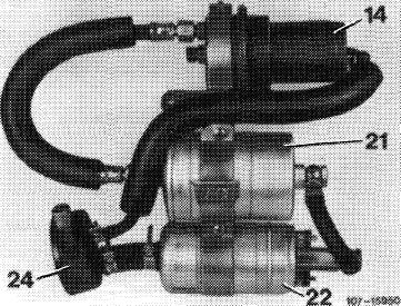
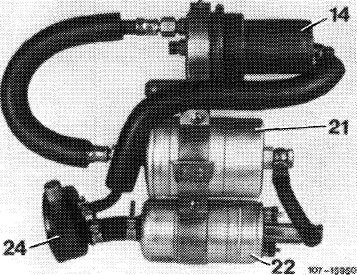
Fuel pump assembly with hose between pump and filter
1 Unscrew protective case.
2 Pinch fuel hoses with clamps.
|
 |
|||
|
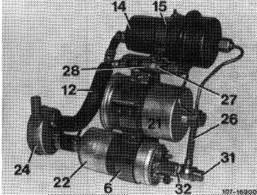
14 Pressure reservoir
21 Filter
22 Fuel pump 24 Damper
|
||||
|
|
||||
|
3 Unscrew fuel pump assembly on both front anti-vibration buffers.
4 Unscrew fuel hose on pump.
5 Screw check valve (32) with new copper sealing ring (33) to fuel pump.
|
 |
|||
|
|
||||
|
07.3.2 lla-283/2
|
F 2
|
|||
|
|
||||
|
|
|||
|
6 Clip fuel pump in holder approx. 15 mm to the left (so that closing nut is no longer chafing against protective case) and mount fuel hose with 2 new copper sealing rings and closing nut to check valve (while applying counterhold to check valve). Hollow screw is no longer installed.
Note: Plastic sheet or plastic sleeve of pump and filter should project on holder on both sides and must be replaced if damaged. For this purpose, remove pump and filter.
|
 |
||
|
|
|||
|
7 Tighten fuel pump and filter in holder and mount holder on anti-vibration buffers.
8 Remove clamps from fuel hoses.
9 Run engine and check system for leaks.
10 Mount protective case. Make sure that fuel hose is not chafing against protective case.
|
|||
|
|
|||
|
07.3.2 I la-283/3 F2
|
|||
|
|
|||