Checking and correcting adjustment of TDC transmitter
|
|
||||||
|
03—345 Checking and correcting adjustment of TDC transmitter
|
||||||
|
|
||||||
|
Tightening tosque
|
Nm
|
|||||
|
|
||||||
|
Bolts and capped nuts for cylinder head cover
|
||||||
|
|
||||||
|
Special tools
|
||||||
|
|
||||||
|
TDC tester
|
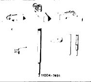 |
110 589 10 21 00
|
||||
|
|
||||||
|
Locating device for adjusting slide (2nd version of adjusting slide)
|
 |
116 589 19 21 00
|
||||
|
|
||||||
|
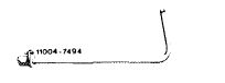
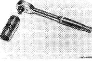
27 mm socket to turn engine
|
 |
001 589 65 09 00
|
||||
|
|
||||||
|
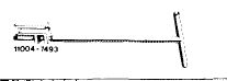
Locating device for TDC transmitter (1st version of adjusting slide)
|
 |
110 589 08 21 00
|
||||
|
|
||||||
|
Guide for TDC transmitter (1st version of adjusting slide)
|
 |
110 589 06 61 00
|
||||
|
|
||||||
|
Note
|
 |
|||||
|
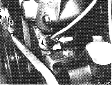
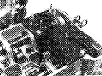
With the crankshaft position at 20° the TDC transmitter must be exactly above the TDC pin in the vibration damper (arrow).
Distance between TDC transmitter and guide pin in vibration damper 0.2—2.0 mm.
|
||||||
|
2nd version of adjusting slide
|
||||||
|
|
||||||
|
03.2-345/1 F 3
|
||||||
|
|
||||||
|
|
|||
|
The adjustment of the TDC transmitter must be checked and corrected:
a) when replacing TDC transmitter adjusting slide,
b) when replacing crankshaft with balance disc and vibration damper, and
c) when completing a partial engine.
|
 |
||
|
1st version of adjusting slide
|
|||
|
|
|||
|
Checking
|
 |
||
|
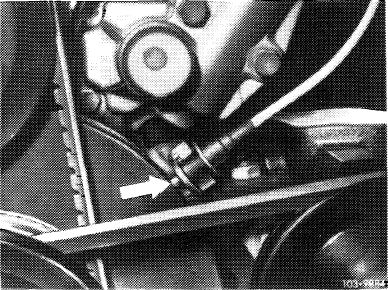
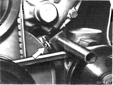
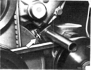
1 Unscrew TDC transmitter (arrow).
|
|||
|
|
|||
|
2 Pull out TDC transmitter.
Note: TDC transmitters (1st version), which are fastened with a socket head cap screw, must be loosened and removed with guide 110 ir89 06 61 00.
|
 |
||
|
|
|||
|
3 Take off cylinder head cover.
|
|||
|
|
|||
|
4 Unscrew spark plug of 1st cylinder.
|
 |
||
|
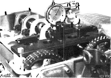
5 Screw-on tester above 1st cylinder.
|
|||
|
|
|||
|
03.2-345/2 F 3
|
|||
|
|
|||
|
|
|||
|
6 Guide in gage extension, do not clamp.
|
 |
||
|
|
|||
|
7 Insert adjusting pin (1) and press down.
|
 |
||
|
|
|||
|
8 Turn crankshaft with tool combination until adjusting pin is at its highest point.
The piston is at TDC.
|
 |
||
|
|
|||
|
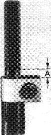
9 Clamp the gage extension in the tester that distance A will be about 5 mm when the adjusting pin is pressed down.
|
 |
||
|
|
|||
|
03.2-345/3 F 3
|
|||
|
|
|||
|
|
|||
|
10 Remove adjusting pin. Insert dial gage and clamp it with preload of about 5 mm.
11 Turn crankshaft and adjust TDC accurately with dial gage.
Always turn crankshaft in direction of rotation.
12 Turn dial gage scale until needle points to 0.
13 Continue turning crankshaft until dial gage goes back by 3.07 mm.
|
 |
||
|
|
|||
|
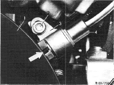
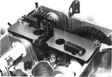
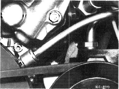
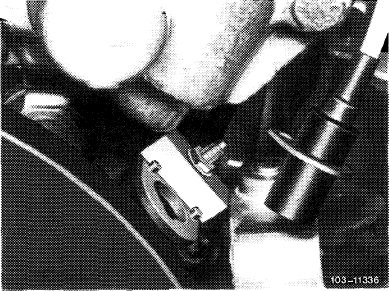
14 Insert locating device in adjusting slide.
Pin of vibration damper should engage in groove of locating device (arrow).
|
 |
||
|
2nd version of adjusting slide, locating device 116 589 19 21 00
|
|||
|
|
|||
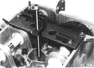
|
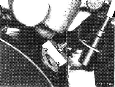
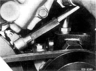
Note: Use locating device 110 589 08 21 00 for 1st version of adjusting slide.
|
 |
||
|
1st version of adjusting slide, locating device 110 589 08 21 00
|
|||
|
|
|||
|
Correcting
|
iflff
|
||
|
15 Loosen adjusting slide and displace until pin of vibration damper enters groove of locating device.
|
|||
|
|
|||
|
03.2-345/4 F 3
|
|||
|
|
|||
|
|
|||
|
16 Tighten adjusting slide and remove locating device.
17 Install and fasten TDC transmitter.
|
 |
||
|
|
|||
|
Note: For 1st version of adjusting slide install the TDC transmitter with guide 110 589 06 61 00 and fasten with a socket head cap screw.
|
 |
||
|
|
|||
|
03.2-345/5 F 3
|
|||
|
|
|||