Operation
|
|
||
|
07.3-500 Operation
|
||
|
|
||
|
A. Decel shutoff
|
||
|
|
||
|
General
|
||
|
|
||
|
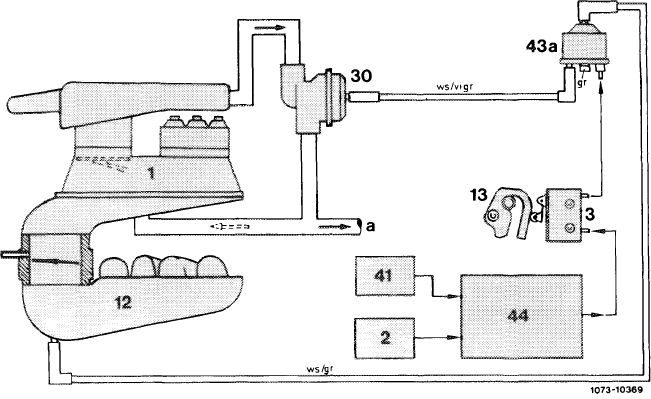
During deceleration, the switchover valve located in vacuum line between intake manifold and decel shut-off valve is activated by means of a microswitch and switched to passage.
The required air for decel operation is sucked in through decel shutoff valve switch which is opened by intake manifold vacuum, while bypassing the air flow sensor plate. The air flow sensor plate remains in zero position, that is, no fuel is injected.
|
||
|
|
||
|
Decel shutoff comprises the following components:
• Decel shutoff valve (30).
• Electronic control unit (fuel pump relay) for decel shutoff (44).
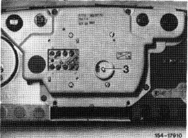
• Microswitch (3).
• Switchover valve (43a)
• Impulse transmitter (41) tachometer.
|
||
|
|
||
|
07.3.2 lla-500/1 F 2
|
||
|
|
||
|
|
|||||
 |
|||||
|
|
|||||
|
1 Mixture controller 30
2 Transistorized switching unit 41
3 Micros witch 43a
12 Intake manifold 44
13 Slotted lever a
|
Decel shutoff valve Color code
Impulse transmitter tachometer gr = gray
Switchover valve decel shutoff vi = purple
Fuel pump relay ws = white To idle speed air distributor
|
||||
|
|
|||||
|
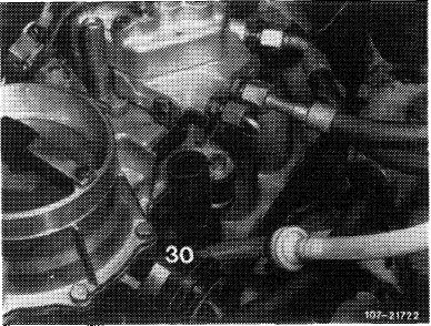
Decel shutoff valve
|
 |
||||
|
During deceleration (coasting) the decel shutoff valve (30) connects the air cleaner with the idle speed air system. As a result, with decel shutoff valve open, the air required by engine under deceleration is taken directly from air cleaner while bypassing the air flow sensor plate (refer to function diagram).
|
|||||
|
|
|||||
|
The air flow sensor plate is not deflected and is in zero position. The fuel feed to the injection valves is therefore interrupted (control slits closed).
|
|||||
|
|
|||||
|
07.3.2 lla-500/2
|
F 2
|
||||
|
|
|||||
|
|
|||
|
The decel shutoff will be operational under the following conditions:
When decelerating (coasting) without air conditioning above 1100/min,and with air conditioning above 1300/min. At a driving speed above 30 km/h.
If these operating conditions are changed, e.g. by accelerating, the decel shutoff will become effective again when an engine speed of 1600/min without air conditioning, and of 1800/min with air conditioning, are exceeded first and the speed was higher than 35 km/h.
|
|||
|
|
|||
|
Decel shutoff is controlled by an electronic control unit (44), which is integrated in fuel pump relay.
|
 |
||
|
Model 107
|
|||
|
|
|||
|
Model 123
|
 |
||
|
|
|||
|
Model 126
|
 |
||
|
|
|||
|
07.3.2 I la-500/3 F2
|
|||
|
|
|||
|
|
|||||
|
The signal for the engine speed is tapped at switching unit of transistorized ignition system (TD).
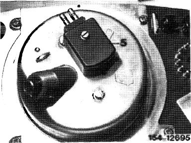
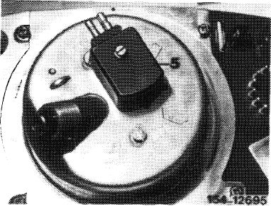
On model 123 with mechanically driven tachometer, the vehicle speed is picked up by an impulse transmitter (5), on model 107 and 126 at electronic tachometer.
|
 |
||||
|
Model 123
|
|||||
|
|
|||||
|
Model 107, 126
|
 |
||||
|
|
|||||
|
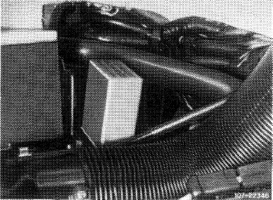
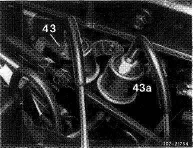
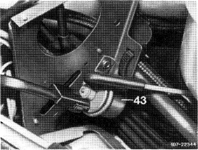
Switchover valve
|
 |
||||
|
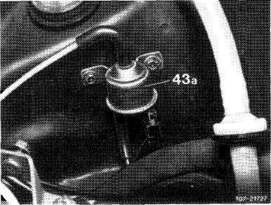
The switchover valve (43a) attached at front end is an electromagnetic valve.
With the microswitch closed and under the conditions named above, voltage is switched to switchover valve by way of control unit. The intake manifold vacuum acts on decel shutoff valve and opens the bypass line from air cleaner to air guide housing. The connection is interrupted the moment the voltage drops.
Model 123
|
|||||
|
|
|||||
|
Layout model 107 (refer to 07.3-140).
|
Model 126
|
 |
|||
|
|
|||||
|
07.3.2 lla-500/4
|
F 2
|
||||
|
|
|||||
|
|
|||
|
Micros witch
|
 |
||
|
The microswitch is located at regulation in idle path range of slotted lever.
With the accelerator pedal in idle speed position and under the conditions named above, the circuit is closed and the decel shutoff is triggered.
When the accelerator pedal is operated, the switch opens already before the throttle valve opens and the decel shutoff will be interrupted. That is, combustion starts again before the throttle valve opens. As a result, any cutting-in jerk will be avoided.
|
|||
|
|
|||
|
B. Idle speed stabilization with rpm increase following start
|
|||
|
|
|||
|
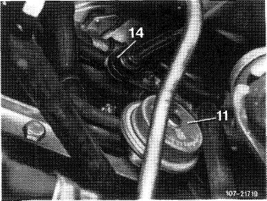
A decel circulating air valve (11) is installed for idle speed stabilization, as well as for an rpm increase after starting.
The valve is located on a holder behind ignition distributor below intake manifold.
|
 |
||
|
|
|||
|
Decel circulating air valve
|
|||
|
|
|||
|
The decel circulating air valve is controlled by the intake manifold vacuum. While bypassing the throttle valve and the idle speed adjusting screw, metered air from air guide housing is guided via contour hoses and the idle speed air distributor to the idle speed air ducts in intake manifold.
|
|||
|
|
|||
|
07.3.2 Ila-500/5 F2
|
|||
|
|
|||
|
|
|||
 |
|||
|
|
|||
|
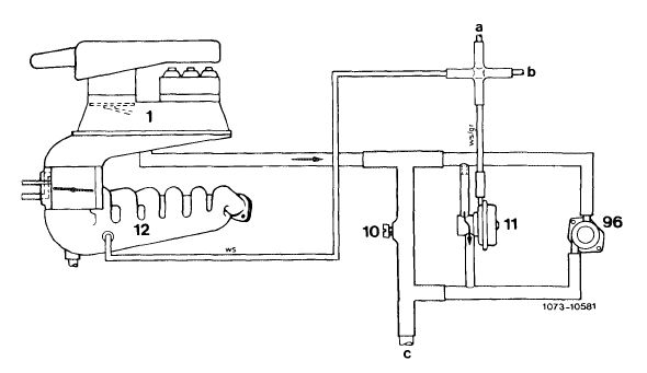
1 Mixture controller
I 0 Idle speed air screw
I1 Decel circulating air valve 1 2 Intake manifold
96 Auxiliary air valve
|
a Conncetion switchover valve decel shutoff Color code
b Connection switchover valve rpm increase gr = gray
air-conditioning system ws = white c To idle speed air duct in intake manifold
|
||
|
|
|||
|
Operation
|
|||
|
|
|||
|
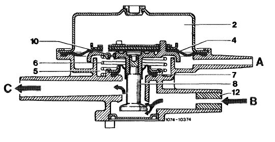
Rpm increase after start.
With engine stopped, atmopheric pressure prevails in lower and upper diaphragm chamber. When the engine is started, a vacuum will be built-in in lower diaphragm chamber (5) and will overcome the contact pressure of compression spring (6). Valve (8) is pushed in downward direction and the path for the bypass air from air guide housing to intake manifold will be cleared. This increased charge will also increase the engine speed at idle for a short period.
As soon as the vacuum in the two diaphragm chambers is again balanced by way of orifice (10), valve (8) will be pushed upwards by compression spring (6) and closed.
|
|||
|
|
|||
|
07.3.2 Ila-500/6 F2
|
|||
|
|
|||
|
|
|||
|
2 Upper diaphragm chamber
4 Diaphragm
5 Lower diaphragm chamber
6 Compression spring
7 Sealing diaphragm
8 Valve 10 Orifice
12 Throttle (restriction)
A Vacuum connection
B Air guide housing inlet
C To contour hose idle speed air distributor
|
 |
||
|
|
|||
|
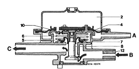
Rpm stabilization from higher speed to idle speed
 |
|||
|
|
|||
|
The decel circulating air valve delays adaptation to lower idle speed after accelerating, since the vacuum in the lower diaphragm chamber (5) increases faster than the compensating process by means of the upper diaphragm chamber via orifice (10).
|
|||
|
|
|||
|
The adjusting force of the vacuum will overcome the contact pressure of compression spring (6). Valve (8) is pushed in downward direction and the bypass air can be sucked in by the engine through the idle speed ducts. Valve (8) will close following pressure compensation between upper and lower diaphragm chamber (2 and 5) via orifice (10).
|
|||
|
|
|||
|
07.3.2 Ila-500/7 F2
|
|||
|
|
|||
|
|
||||
|
C. Idle speed stabilization on engines with refrigerant compressor
|
||||
|
|
||||
|
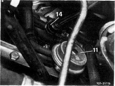
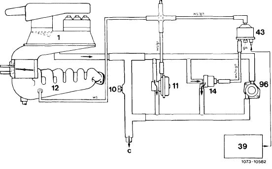
Vehicles with air conditioning/automatic climate control are provided with a bypass valve (14) for rpm stabilization at idle.
Bypassing the throttle valve, the air measured by the air flow sensor plate is guided to intake manifold (12) by bypass valve (14). With the air-conditioning system/ automatic climate control switched on, the electric switchover valve (43) is energized and will connect the bypass valve (14) to the vacuum connection on intake manifold. The bypass valve will open under influence of intake manifold vacuum. Bypassing the throttle valve, the engine will aspirate more air and the idle speed will be increased.
|
||||
|
|
||||
 |
||||
|
|
||||
 |
||||
|
|
||||
|
1 Mixture controller 10 Idle speed air screw 1 2 Intake manifold 14 Bypass valve air conditioning 39 Relay air conditioning 43 Switchover valve
rpm increase air conditioning 96 Auxiliary air valve
|
a Connection switchover valve-decel shutoff c To idle air duct in intake manifold d Connection decel circulating air valve
|
Color code gn = green vi = purple ws = white
|
||
|
|
||||
|
07.3.2 lla-500/8 F 2
|
||||
|
|
||||
|
|
|||
|
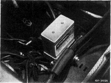
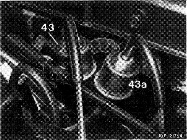
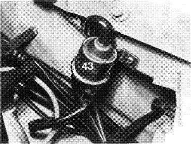
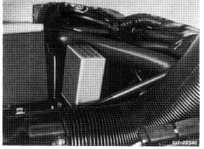
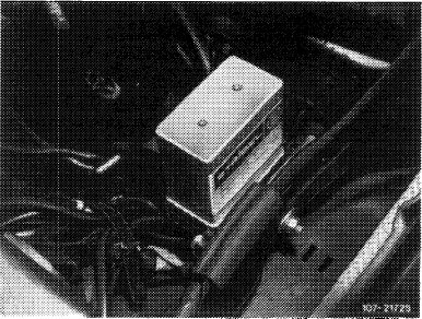
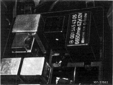
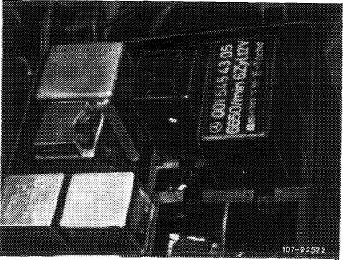
Layout of switchover valve (43)
|
 |
||
|
Model 107
|
|||
|
|
|||
|
Model 123
|
iC-t 21728
|
||
|
|
|||
|
Model 1 26
|
 |
||
|
|
|||
|
07.3.2 Ila-500/9 F2
|
|||
|
|
|||
|
|
||||
|
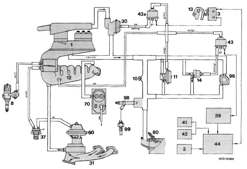
D. Function diagram decel shutoff, idle speed stabilization, EGR
|
||||
|
|
||||
 |
||||
|
|
||||
|
1 Mixture controller 41
2 Transistorized switching unit 42
3 Micro switch 43 8 Ignition distributor
10 Idle speed air screw 43a
11 Decel circulating air valve 44
12 Intake manifold 60 1 3 Slotted lever 70 14 Bypass valve air conditioning 80
30 Decel shutoff valve 96
31 Exhaust manifold 98 37 Thermovalve 50 °C EGR 99 39 Relay air conditioning i
|
Impulse transmitter mechanical tachometer Color code
Electronic tachometer br = brown
Switchover valve gn = green
rpm increase air conditioning gr =gray
Switchover valve decel shutoff rs = pink
Fuel pump relay rt = red
EGR valve sw = black
Warm-up compensator vi = purple
Injection valve ws = white Auxiliary air valve Cold start valve Thermo time switch To leak line (atmosphere)
|
|||
|
|
||||
|
07.3.2 lla-500/10
|
F 2
|
|||
|
|
||||
|
|
||||
|
E. Fuel pump relay
|
||||
|
|
||||
|
The fuel pump relay for supplying voltage to fuel pump has three or four functions:
1. Activation of fuel pump while starting and with the engine running.
In parallel with fuel pump, the warm-up compensator is likewise activated.
2. Rpm limitation after attaining max. engine speed.
3. Switching-off fuel pump as soon as there are no more impulses via terminal TD of switching unit: TD = transistor speed.
4. Control of decel shutoff. (starting September 1981).
|
||||
|
|
||||
|
Wiring diagram prior to September 1981
1 Fuel pump relay
2 Fuel pump
3 Warm-up compensator 4Switching unit (TSZ)
TSZ = transistorized switching unit
|
 |
|||
|
|
||||
|
07.3.2 lla-500/11
|
F2
|
|||
|
|
||||
|
|
|||||
 |
|||||
|
|
|||||
|
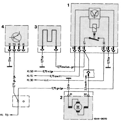
Wiring diagram starting September 1981 — model 123
|
|||||
|
|
|||||
|
1 Fuel pump relay
2 Thermo time switch
3 Cold starting valve
4 Warm-up compensator
5 Switchover valve
6 Micros witch
|
a To output starter lockout and
backup lamp switch
b Transmitter mechanical tachometer
c Fuel pump
d Fuse 12 terminal 15 access
e Refrigerant compressor
f Cable connector engine terminal 30
g Cable connector terminal TD
h Cable connector engine terminal 50
|
Color code bl =blue br = brown ge = yellow gn = green gr =gray rs = pink rt = red sw = black vi = purple ws = wh ite
|
|||
|
|
|||||
|
07.3.2 lla-500/12
|
F 2
|
||||
|
|
|||||
|
|
||||
 |
||||
|
|
||||
|
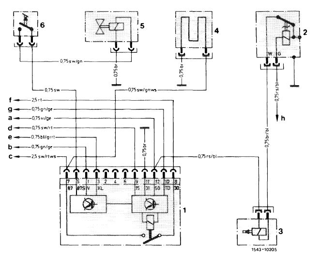
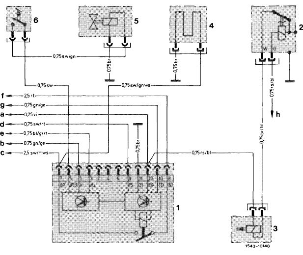
Wiring diagram starting September 1981 – model 107, 126
|
||||
|
|
||||
|
1 Fuel pump relay
2 Thermo time switch
3 Cold starting valve
4 Warm-up compensator
5 Switchover valve
6 Microswitch
|
a Cable connector engine terminal 50
b Transmitter electronic tachometer
c Fuel pump
d Fuse 14 terminal 15 access
e Refrigerant compressor
f Cable connector terminal 30
g Cable connector terminal TD
h Cable connector engine terminal 50
|
Color code bl =blue br = brown ge = yellow gn = green gr =gray rs = pink rt = red sw = black vi = purple ws = white
|
||
|
|
||||
|
07.3.2 lla-500/13 F2
|
||||
|
|
||||
|
|
||||
|
1. Activation of fuel pump while starting and with engine running
|
 |
|||
|
While starting, the fuel pump relay is activated via terminal 50 and with the engine running via terminal TD of ignition switching unit.
|
||||
|
Model 107
|
||||
|
|
||||
|
While starting, the fuel pump relay is activated via terminal 50, because the pertinent parallel activation of fuel pump relay via terminal TD is not enough at engine speed below approx. 80/min. The pulse sequence of terminal TD is too low to keep contacts 30 and 87 in pump relay continuously closed.
|
 |
|||
|
Model 123
|
||||
|
|
||||
|
At speeds above approx. 80/min, the frequency of the pulses is so high that contacts 30 and 87 in fuel pump relay remain continuously closed.
The warm-up compensator is also activated in parallel with fuel pump.
|
 |
|||
|
Model 126
|
||||
|
|
||||
|
2. Rpm limitation after attaining max. engine speed
|
||||
|
|
||||
|
After attaining a given pulse sequence according to max. engine speed, contacts 30 and 87 for fuel pump are interrupted. Fuel pump is deenergized and will switch off.
|
||||
|
|
||||
|
07.3.2 lla-500/14
|
F 2
|
|||
|
|
||||
|
|
||||
|
3. Switching-off fuel pump as soon as there are no pulses via terminal TD of switching unit
|
||||
|
|
||||
|
As a safety circuit, one second after last impulse of terminal TD, contacts 30 and 87 in fuel pump relay are interrupted. The pump is deenergized and switches off.
|
||||
|
|
||||
|
4. Control of decel shutoff starting September 1981
|
 |
|||
|
Decel shutoff is controlled by an electronic control unit which is integrated in fuel pump relay.
The signal for the engine speed is picked up at switching unit of transistorized ignition system (TD).
|
||||
|
|
||||
|
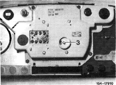
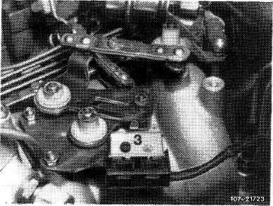
On model 123 with mechanically driven tachometer, the vehicle speed is picked up by an impulse transmitter (5), on model 107 and 126 on impulse transmitter connection (3) of electronic tachometer.
|
 |
|||
|
Model 123
|
||||
|
|
||||
|
Model 107, 126
|
 |
|||
|
|
||||
|
07.3.2 lla-500/15
|
F 2
|
|||
|
|
||||
|
|
|||||
|
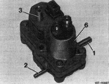
F. Warm-up compensator
|
|||||
|
|
|||||
|
The warm-up compensator regulates the control pressure which acts on control piston and serves for enriching the fuel mixture in warm-up stage and at full load.
The warm-up compensator is connected to two fuel lines, the control pressure line and the return flow line.
|
|||||
|
|
|||||
|
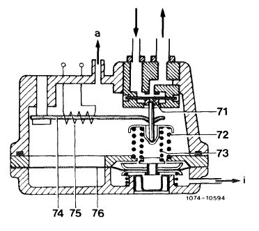
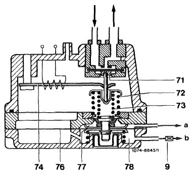
The control pressure acts on top of diaphragm valve (71), which throttles the outflow cross section of return flow line.
Two valve springs (72 and 73) operating at the bottom are adapted to normal control pressure.
|
 |
||||
|
71 Diaphragm valve
72 Outer valve spring
73 Inner valve spring
d To intake manifold (vacuum) i To leak line (atmosphere)
|
74 Bimetallic strip
75 Heater coil
76 Vacuum diaphragm
|
||||
|
|
|||||
|
A bimetallic strip (74) provided with a heater coil (75) is installed for enrichment during warm-up stage. The cold bimetallic strip acts against valve springs (72 and 73), so that diaphragm (71) will open and the control pressure will be reduced. Heating up will successively reduce the effect of the bimetallic spring until the control pressure has attained its normal value.
|
|||||
|
|
|||||
|
Full load enrichment
|
|||||
|
|
|||||
|
Prior to September 1981
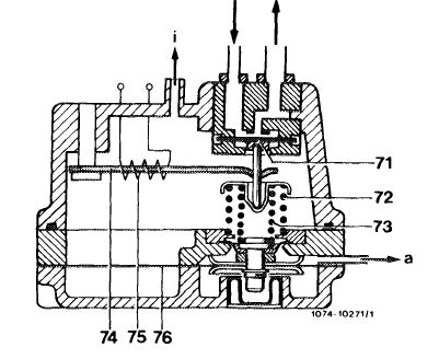
For full load enrichment, the warm-up compensator is separated into two chambers by means of a vacuum diaphragm (76). Intake vacuum „a” is effective in upper chamber. The lower chamber is vented via connection „\”.
To prevent the entry of dirt or water, the vent connection is connected to leak line of fuel damper.
|
|||||
|
|
|||||
|
07.3.2 lla-500/16
|
F2
|
||||
|
|
|||||
|
|
||||
|
At idle and in partial load range the upper chamber is under influence of vacuum and vacuum diaphragm (76) rests against upper stop. In this position, the spring force establishes the normal value of the control pressure.
At full load, the vacuum in upper chamber is exhausted and the vacuum diaphragm (76) is moving in downward direction. The force of the inner valve spring (73) is getting less, and the control pressure is thereby reduced to full load value.
|
 |
|||
|
|
||||
|
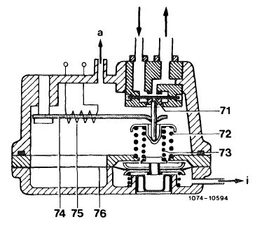
Starting September 1981
The lower chamber of the warm-up compensator has a vacuum diaphragm (76) which is controlled by the vacuum. Vacuum connection „a” is in lower chamber. The inner compression spring is relieved under influence of decreasing vacuum (increasing load).
|
||||
|
|
||||
|
71 Diaphragm valve
72 Outer valve spring
73 Inner valve spring
74 Bimatallic strip
75 Heater coil
76 Vacuum diaphragm
a To intake manifold (vacuum)
i To leak line (atmosphere)
|
 |
|||
|
|
||||
|
Under influence of resulting low control pressure (increase of outflow cross section) a low force is acting on control piston in fuel distributor. As a result, the air flow sensor plate is further deflected at the same air flow rate and a larger quantity of fuel will be supplied (mixture enrichment).
Connection „i” on upper chamber serves for venting. To prevent the entry of dirt or water, the vent connection is connected to leak line of fuel damper.
|
||||
|
|
||||
|
07.3.2 tla-500/17
|
F 2
|
|||
|
|
||||
|
|
||||
|
Acceleration enrichment
|
 |
|||
|
(7) starting 1981 <@> 1980/81
To obtain an additional mixture enrichment in warm-up stage during acceleration, the warm-up compensator has been provided with an acceleration enrichment.
1 Connection upper chamber
2 Connection lower chamber
3 Vent to atmosphere
6 Warm-up compensator
|
||||
|
|
||||
|
The full load enrichment via warm-up compensator is no longer employed and is now activated via throttle valve switch.
Acceleration enrichment is controlled in dependence of vacuum under a coolant temperature of 50 °C.
|
 |
|||
|
9 Throttle (restriction)
71 Diaphragm valve
72 Outer valve spring
73 Inner valve spring
74 Bimetallic spring 77 Vacuum diaphragm
|
77 Upper chamber
78 Lower chamber
a Connection upper chamber b Connection lower chamber
|
|||
|
|
||||
|
Two springs are pressing down on control diaphragm (71) in warm-up compensator, the outer spring (72) is firmly supported in housing and the inner spring (73) is loaded or unloaded in dependence of vacuum.
A chamber in warm-up compensator housing-lower half is divided into an upper chamber (77) and a lower chamber (78) by a diaphragm. Both chambers are connected to intake manifold vacuum, with a choke (9) located in vacuum line to lower chamber.
At constant speed, the diaphragm (76) rests against upper stop. As a result, the vacuum in upper and lower chamber is the same.
During acceleration, the vacuum in the upper chamber decreases faster than in the lower chamber under influence of choke (9).
The inner spring is relieved up to pressure compensation of the two chambers and the pressure on control diaphragm is therefore lower.
|
||||
|
|
||||
|
07.3.2 lla-500/18 F 2
|
||||
|
|
||||
|
|
|||
|
As a result of the now lower control pressure (enlargement of outflow cross section) a lower force will act on control piston in fuel distributor. Consequently, the air flow sensor plate is further deflected while the air flow rate remains the same, so that a larger amount of fuel will be supplied (mixture enrichment).
Thermo valve (37) opens at a coolant temperature of 50 °C. The lower diaphragm chamber of the warm-up compensator is vented and the acceleration enrichment is cancelled. Both springs are pressing against control diaphragm and the control pressure obtains its normal value.
|
|||
|
|
|||
|
Full load enrichment by throttle valve switch
|
 |
||
|
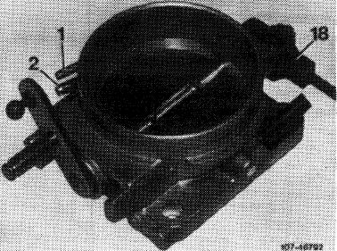
The throttle valve switch is attached to throttle valve housing and has two functions: Idle speed and full load contact.
|
|||
|
1 Connection vacuum advance
2 Draw-off connection charcoal canister 18 Throttle valve switch
|
|||
|
|
|||
|
Idle speed contact
The idle speed contact on throttle valve switch results in a narrowing-down of the control range in control unit and thereby in a stabilization of the idle speed.
|
|||
|
|
|||
|
Full throttle contact
If the vehicle is driven in full throttle range (throttle valve against full throttle stop), a fixed on-off ratio of 60 to 40 (slightly richer) is set in control unit via the full throttle contact.
|
|||
|
|
|||
|
G. Light alloy fuel distributor
|
|||
|
|
|||
|
The characteristic of the fuel distributor and the air funnel in air flow sensor has been changed in full load range. Consumption in full load range has been reduced as a result of improved adaptation.
|
|||
|
|
|||
|
07.3.2 lla-500/19 F2
|
|||
|
|
|||
|
|
|||
|
A fabric diaphragm is installed between upper and lower half. On top of fuel distributor are 6 closing screws with adjusting screws for differential pressure valves underneath. The differential pressure valves are set by manufacturer, adjustments are not permitted.
The connecting system of the injection line has been changed and now corresponds to that of 8-cylinder engines.
|
 |
||
|
|
|||
|
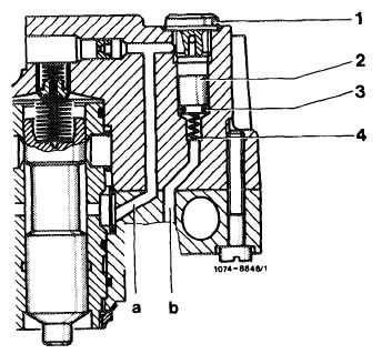
In addition, the fuel distributor upper half has been provided with a pressure compensating valve (arrow), as well as a compression spring above control piston.
On gray iron fuel distributor the compression spring is installed since February 1979, and on light alloy fuel distributor since start of series.
|
 |
||
|
|
|||
|
The pressure compensating valve is closed as long as the fuel system is under pressure.
The pressure compensating valve will open in the event of a pressure drop „after a long period of inoperation and cooling-down of fuel „below 0.3—0.5 bar gauge pressure.
Piston (2) is lifted, pressure compensation proceeds between system pressure and return flow pressure via piston gap.
This will prevent that the control piston in fuel distributor is lifted in direction of full load with the engine stopped and that a heavy mixture enrichment occurs during cold start.
|
 |
||
|
1 Closing plug
2 Piston
3 O-ring
4 Compression spring a System pressure
b Return flow
|
|||
|
|
|||
|
07.3.2 I la/500/20
|
|||
|
|
|||