Renewal and tensioning of V-belt
|
|
||||||||||||||||||||||||||||||||||||||||||||||||||||||
|
13-340 Renewal and tensioning of V-belt
|
||||||||||||||||||||||||||||||||||||||||||||||||||||||
|
|
||||||||||||||||||||||||||||||||||||||||||||||||||||||
|
||||||||||||||||||||||||||||||||||||||||||||||||||||||
|
|
||||||||||||||||||||||||||||||||||||||||||||||||||||||
|
1) Power steering pump with cast-on reservoir.
2) Standard starting 5.1978.
3) Version 1 (swivelling tensioning roller), of models 114.060/062/072/073.
|
 |
|||||||||||||||||||||||||||||||||||||||||||||||||||||
|
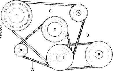
1 Crankshaft 4 Refrigerant compressor
2 Water pump 5 Tensioning roller
3 Alternator 6 Power steering pump
|
||||||||||||||||||||||||||||||||||||||||||||||||||||||
|
|
||||||||||||||||||||||||||||||||||||||||||||||||||||||
|
||||||||||||||||||||||||||||||||||||||||||||||||||||||
|
|
||||||||||||||||||||||||||||||||||||||||||||||||||||||
|
J) On 65-A alternator (T)1979, with KW-pulley
110 032 08 04 (formerly 123 032 01 04). 2) Standard starting 5.1978.
|
 |
1133-5642 rt
|
||||||||||||||||||||||||||||||||||||||||||||||||||||
|
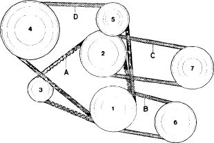
Model year 1974-1976
|
||||||||||||||||||||||||||||||||||||||||||||||||||||||
|
1 Crankshaft
2 Water pump
3 Alternator
4 Refrigerant compressor
|
5 Tensioning roller
6 Power steering pump
7 Air pump
|
|||||||||||||||||||||||||||||||||||||||||||||||||||||
|
|
||||||||||||||||||||||||||||||||||||||||||||||||||||||
|
13.2-340/1 F3
|
||||||||||||||||||||||||||||||||||||||||||||||||||||||
|
|
||||||||||||||||||||||||||||||||||||||||||||||||||||||
|
|
||||||
|
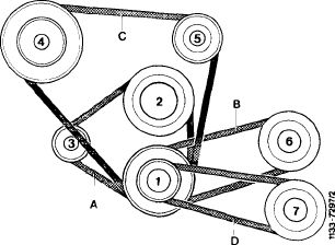
Model year 1977/78
1 Crankshaft
2 Water pump
3 Alternator
4 Compressor
|
5 Roller
6 Power steering pump
7 Air pump
|
 |
||||
|
|
||||||
|
Special tools
|
||||||
|
|
||||||
|
Wrench socket 8 mm, 1/2″ square, 130 mm long
|
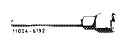 |
000 589 33 07 00
|
||||
|
|
||||||
|
Note
|
||||||
|
|
||||||
|
Measuring instrument „Krikit” is recommended for checking V-belt tension.
|
||||||
|
|
||||||
|
Handling of measuring instrument
|
 |
|||||
|
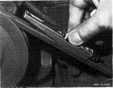
For checking V-belt tension the measuring instrument can be held in different ways:
a) With thumb and forefinger on rubber loop, with finger tips resting on push button.
|
||||||
|
|
||||||
|
13.2-340/2 F3
|
||||||
|
|
||||||
|
|
||||
|
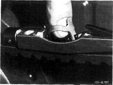
b) With forefinger from above in rubber loop.
|
 |
|||
|
|
||||
|
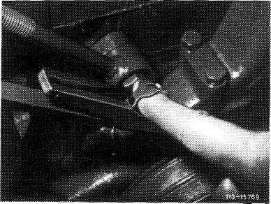
c) With forefinger laterally between rubber loop and push button.
|
 |
|||
|
|
||||
|
Checkup
|
 |
|||
|
1
|
Lower indicating arm on measuring instrument.
|
|||
|
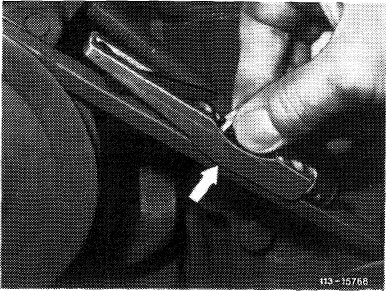
2 Place measuring instrument on V-belt in center between pulleys. Lateral stop on measuring instrument should rest laterally against V-belt (arrow).
|
||||
|
|
||||
|
Attention!
On double belt drive make sure that measuring instrument rests only on one V-belt.
3 Exert uniform vertical pressure on top of V-belt by means of push button until click spring disengages audibly (or noticeably).
Note: Upon disengagement of click spring do not continue pushing measuring instrument, since this will result in a wrong indication.
|
||||
|
|
||||
|
13.2-340/3 F3
|
||||
|
|
||||
|
|
|||
|
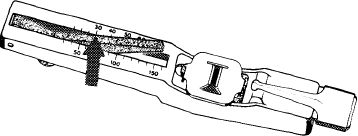
4 Lift measuring instrument carefully from V-belt. Prevent impacts which may change position of indicating arm.
5 Read tension value on point of intersection of indicating arm on upper scale (arrow).
The specified adjusting values refer to KG-scale of measuring instrument.
|
 |
||
|
2134-1218/1
|
|||
|
|
|||
|
Tensioning
|
 |
||
|
Belt A Alternator — coolant pump up to and including 1974
1 Loosen nut (2) and mounting bolt (arrow).
2 Adjust belt tightness at 6 mm square (1) or hexagon of tightening bolt (3).
3 Tighten nut (2) and mounting bolt (arrow).
|
|||
|
|
|||
|
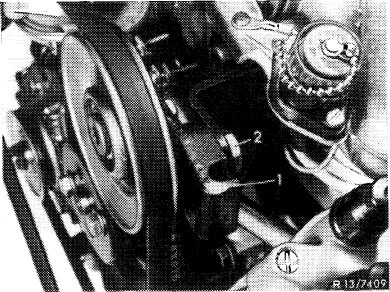
Belt A Alternator — coolant pump starting 1975
1 Loosen nut (1).
2 Adjust belt tightness with tightening bolt (2).
3 Tighten nut (1).
|
 |
||
|
|
|||
|
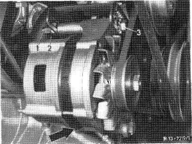
Belt B Power steering pump
|
 |
||
|
1 Loosen mounting bolts (1, 2 and 3).
2 Adjust belt tightness with toothed disc (4).
3 Tighten mounting bolts (1, 2 and 3).
|
|||
|
|
|||
|
13.2-340/4 F3
|
|||
|
|
|||
|
|
|||
|
Belt B Power steering pump
USA version 1974 models
|
 |
||
|
1 Loosen mounting bolt (1).
2 Adjust belt tightness by swinging out power steering pump.
3 Tighten mounting bolt (1).
|
|||
|
|
|||
|
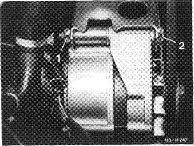
Belt B Power steering pump
USA version 1975/76 models Sweden, Japan version 1976 models
1 Loosen mounting bolt (1).
2 Adjust belt tightness with toothed disc (2).
3 Tighten mounting bolt (1).
|
 |
||
|
|
|||
|
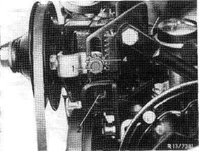
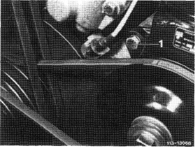
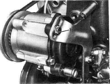
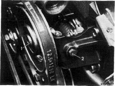
Belt B Power steering pump model 123 Standard version and starting model year 1977
1 Loosen screw (1) on face of power steering.
|
 |
||
|
|
|||
|
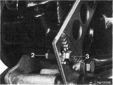
2 Loosen nut (2).
3 Tension belt with tensioning screw (3).
4 Tighten nut (2) and screw (1).
|
 |
||
|
|
|||
|
13.2-340/5 F3
|
|||
|
|
|||
|
|
|||
|
Belt C Air pump
USA version from 1974 – 1976 models Sweden version from 1976 models Japan version from 1976 models
1 Loosen mounting bolt (1).
2 Adjust belt tightness by swinging out air pump.
3 Tighten mounting bolt (1).
|
 |
||
|
|
|||
|
Belt C Air pump starting model year 1977 Australia, Japan, Sweden, USA version
|
113-12671
|
||
|
1 Loosen mounting bolt (1).
|
|||
|
2 Adjust belt tightness by swinging out air pump.
|
|||
|
3 Tighten mounting bolt (1).
|
|||
|
|
|||
|
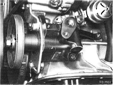
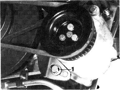
Belt D 1st version compressor
|
 |
||
|
1 Guide an appropriate tool with an approx. 8 mm dia. into opening of holder (1).
2 Loosen mounting bolt (2).
3 Adjust belt tightness by swinging holder (1) clockwise.
4 Tighten mounting bolt (2).
|
|||
|
|
|||
|
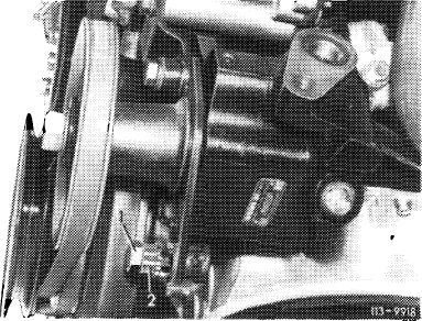
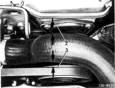
Attention!
Check the following distances of a re-tightened belt. Distance from coolant hose to cover (2) is approx. 5 mm.
Distance from coolant hose to belt roller (3) is approx. 10 mm.
If these distances cannot be reached by loosening the hose clamp (1) and twisting the coolant hose, the tightening device must be converted to the 2nd version.
|
 |
||
|
|
|||
|
13.2-340/6 F3
|
|||
|
|
|||
|
|
|||
|
Belt D Refrigerant compressor version 2
|
 |
||
|
1 Loosen expansion bolt (1).
|
|||
|
2 Adjust belt tightness with tightening bolt (2).
|
|||
|
3 Torque expansion bolt (1) to 16 Nm.
|
|||
|
|
|||
|
Note: A number of vehicles has been delivered with the counternut on the tightening bolt (2). For this version the belt tightness is adjusted with the counter-nut. However, it would be more advantageous to exchange the M 6 x 90 adjusting bolt against a M 6 x 75 bolt, part number 000 933 006 176, and to install this bolt without a counternut.
|
|||
|
|
|||
|
13.2-340/7 F3
|
|||
|
|
|||