Adjustment of regulating linkage
|
|
||||||||||||||||||||||||||||||||||||||||||||||||||||
|
30-300 Adjustment of regulating linkage
|
||||||||||||||||||||||||||||||||||||||||||||||||||||
|
|
||||||||||||||||||||||||||||||||||||||||||||||||||||
|
A. Lefthand steering models 107, 116, 123, 126 Righthand steering models 107, 116, 126
|
||||||||||||||||||||||||||||||||||||||||||||||||||||
|
|
||||||||||||||||||||||||||||||||||||||||||||||||||||
|
Adjusting values in mm
|
||||||||||||||||||||||||||||||||||||||||||||||||||||
|
|
||||||||||||||||||||||||||||||||||||||||||||||||||||
|
||||||||||||||||||||||||||||||||||||||||||||||||||||
|
|
||||||||||||||||||||||||||||||||||||||||||||||||||||
|
Adjustment
|
||||||||||||||||||||||||||||||||||||||||||||||||||||
|
|
||||||||||||||||||||||||||||||||||||||||||||||||||||
|
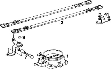
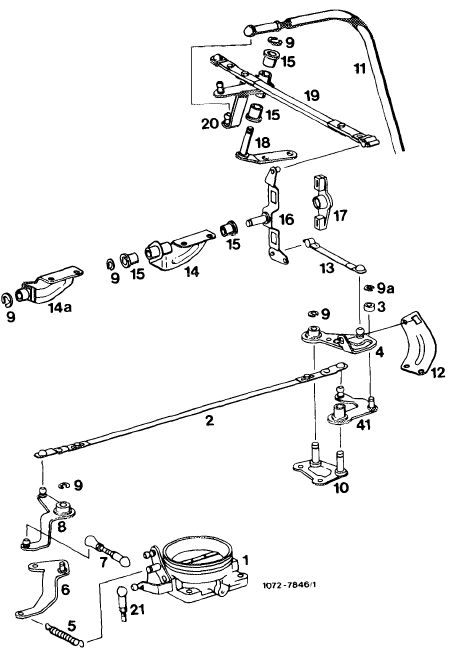
1 Check regulating linkage for easy operation and bends. Replace linkage, if required.
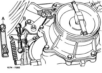
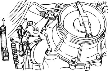
2 Disconnect connecting rod (B) on throttle valve housing. Check whether throttle valve rests against idle speed stop. Reconnect connecting rod free of tension, adjust to specified length, if required.
Note: The connecting rod (B) should be made of round material with screwed-on ball sockets. Replace profilated sheet metal-connecting rod (A).
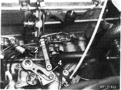
3 Adjust connecting rod (1,2) in such a manner that the rollers (3, 15) in slotted lever (4, 13) are resting free of tension against final stop.
|
 |
|||||||||||||||||||||||||||||||||||||||||||||||||||
 |
||||||||||||||||||||||||||||||||||||||||||||||||||||
|
Model 123
|
||||||||||||||||||||||||||||||||||||||||||||||||||||
|
|
||||||||||||||||||||||||||||||||||||||||||||||||||||
|
30.2 lib—300/1 F2
|
||||||||||||||||||||||||||||||||||||||||||||||||||||
|
|
||||||||||||||||||||||||||||||||||||||||||||||||||||
|
|
|||||||||||||||||||||||||||||||
|
Model 126
|
 |
||||||||||||||||||||||||||||||
|
|
|||||||||||||||||||||||||||||||
|
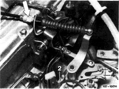
The connecting rod (2a) can now be adjusted on one side only. Pay attention to installation position (refer to Fig.).
|
2a
|
||||||||||||||||||||||||||||||
|
2 1st version 2a 2nd version
|
|||||||||||||||||||||||||||||||
|
13O4-1O7O2
|
|||||||||||||||||||||||||||||||
|
|
|||||||||||||||||||||||||||||||
|
Installation: January 1982
|
|||||||||||||||||||||||||||||||
|
|
|||||||||||||||||||||||||||||||
|
Model
|
Engine
|
|
|||||||||||||||||||||||||||||
|
|
|||||||||||||||||||||||||||||||
|
107
|
110.990
|
000 333
|
000 727
|
012 560
|
|||||||||||||||||||||||||||
|
|
|||||||||||||||||||||||||||||||
|
123.033 123.053 123.093
|
110.988
|
001 431
|
004 447
|
099 669 025 300 010 978
|
|||||||||||||||||||||||||||
|
|
|||||||||||||||||||||||||||||||
|
126.022 126.023
|
110.989
|
001 665
|
009 354
|
053 569
|
|||||||||||||||||||||||||||
|
|
|||||||||||||||||||||||||||||||
|
30.2 llb-300/2 F2
|
|||||||||||||||||||||||||||||||
|
|
|||||||||||||||||||||||||||||||
|
|
|||
|
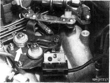
Engines with decel shutoff
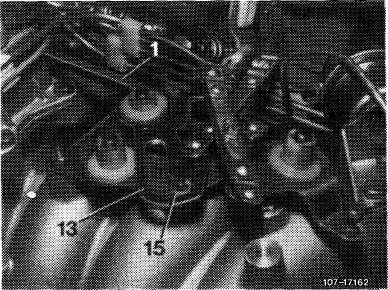
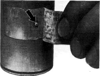
To guarantee operation of microswitch (3) the slotted lever (13) is provided with a restoring spring (arrow). As a result, the slotted lever will return reliably against final stop.
|
 |
||
|
|
|||
|
4 Vehicles with cruise control/Tempomat:
|
 |
||
|
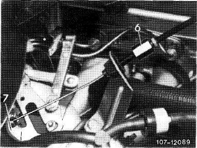
Cruise control/Tempomat, pneumatical
Check whether Bowden wire for cruise control/ Tempomat rests free of tension against regulating lever (7). Adjust by means of adjusting nut (6), if required.
|
|||
|
|
|||
|
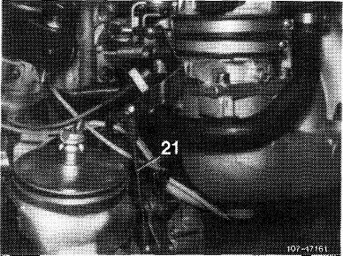
Cruise control/Tempomat, electrical
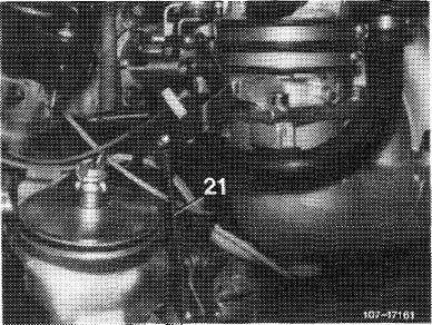
Check whether actuator rests against idle speed stop of cruise control/Tempomat. For this purpose, disconnect pullrod (21) and push lever of actuator clockwise against idle speed stop.
When connecting pullrod (21) make sure that lever of actuator is lifted by approx. 1 mm from idle speed stop. Adjust pullrod, if required.
|
 |
||
|
|
|||
|
Testing and adjusting full throttle stop
|
 |
||
|
Attention!
On vehicles with automatic transmission 722.3 (W 4 A 040) disconnect Bowden wire (11) and reconnect after adjusting full throttle stop.
|
|||
|
|
|||
|
30.2 llb-300/3 F 2
|
|||
|
|
|||
|
|
|||
|
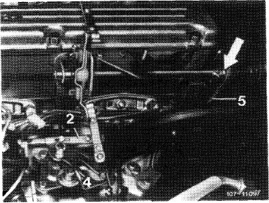
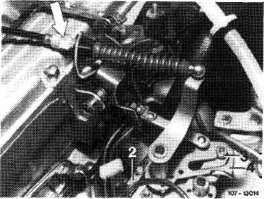
5 With engine stopped, step on accelerator pedal from inside vehicle up to full throttle stop or on automatic transmission up to stop on kickdown switch. Throttle valve lever should rest against full throttle stop. If required, loosen adjusting screw (arrow). Adjust regulating linkage in such a manner that throttle valve lever rests against full throttle stop.
If the full throttle or idle speed stop is not attained with this adjustment, set pushrod (5) from longitudinal regulating shaft to accelerator pedal to specified length, measured from center of ball socket to center of damping ring.
|
 |
||
|
|
|||
|
6 Vehicles with automatic transmission:
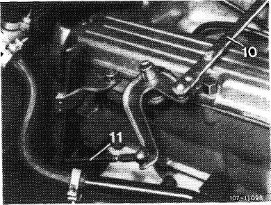
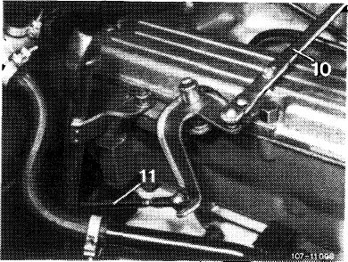
a) Adjust control pressure rod (11) with engine stopped. For this purpose, disconnect control pressure rod, push completely toward the rear against stop and reconnect free of tension. Adjust ball socket, if required.
|
 |
||
|
Control pressure rod with automatic transmission 722.1 (W 4 B 025)
|
|||
|
|
|||
|
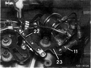
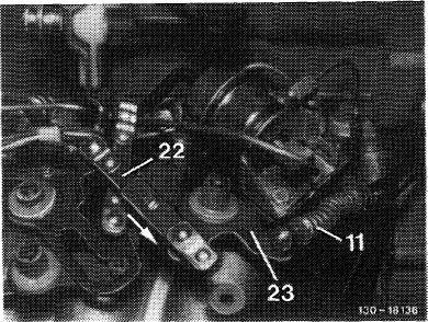
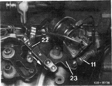
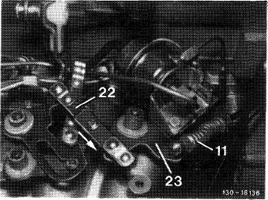
b) Adjust Bowden wire (11) with engine stopped. For this purpose, disconnect connecting rod (22) and pull guide lever (23) in direction of arrow noticeably against idle speed stop on automatic transmission. Reconnect connecting rod (22) free of tension and adjust, if required.
|
 |
||
|
Bowden wire with automatic transmission 722.3 (W 4 A 040)
|
|||
|
|
|||
|
30.2 llb-300/4 F 2
|
|||
|
|
|||
|
|
|||||||||||||||||||||||||||||||||||||||||||||||||||||||||||||||||||||||||||||||||||||||||||||||||||||||||||||||||||
|
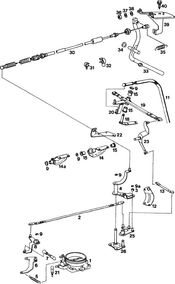
Engine regulating
Lefthand steering models 107,116, 123, 126
Righthand steering models 107, 116
Prior to September 1981
|
|||||||||||||||||||||||||||||||||||||||||||||||||||||||||||||||||||||||||||||||||||||||||||||||||||||||||||||||||||
|
|
|||||||||||||||||||||||||||||||||||||||||||||||||||||||||||||||||||||||||||||||||||||||||||||||||||||||||||||||||||
|
 |
||||||||||||||||||||||||||||||||||||||||||||||||||||||||||||||||||||||||||||||||||||||||||||||||||||||||||||||||||
|
|
|||||||||||||||||||||||||||||||||||||||||||||||||||||||||||||||||||||||||||||||||||||||||||||||||||||||||||||||||||
|
30.2 llb-300/5 F2
|
|||||||||||||||||||||||||||||||||||||||||||||||||||||||||||||||||||||||||||||||||||||||||||||||||||||||||||||||||||
|
|
|||||||||||||||||||||||||||||||||||||||||||||||||||||||||||||||||||||||||||||||||||||||||||||||||||||||||||||||||||
|
|
|||||||||||||||||||||||||||||||||||||||||||||||||||||||||||||||||||||||||||||||||||||||||||||||||||||||||||
|
Starting September 1981
|
|||||||||||||||||||||||||||||||||||||||||||||||||||||||||||||||||||||||||||||||||||||||||||||||||||||||||||
|
|
|||||||||||||||||||||||||||||||||||||||||||||||||||||||||||||||||||||||||||||||||||||||||||||||||||||||||||
|
1073-10647
|
|||||||||||||||||||||||||||||||||||||||||||||||||||||||||||||||||||||||||||||||||||||||||||||||||||||||||||
|
|
|||||||||||||||||||||||||||||||||||||||||||||||||||||||||||||||||||||||||||||||||||||||||||||||||||||||||||
|
|
||||||||||||||||||||||||||||||||||||||||||||||||||||||||||||||||||||||||||||||||||||||||||||||||||||||||||
|
|
|||||||||||||||||||||||||||||||||||||||||||||||||||||||||||||||||||||||||||||||||||||||||||||||||||||||||||
|
30.2 llb-300/6 F2
|
|||||||||||||||||||||||||||||||||||||||||||||||||||||||||||||||||||||||||||||||||||||||||||||||||||||||||||
|
|
|||||||||||||||||||||||||||||||||||||||||||||||||||||||||||||||||||||||||||||||||||||||||||||||||||||||||||
|
|
|||||
|
B. Righthand steering model 123
|
|||||
|
|
|||||
|
Adjusting values in mm
|
|||||
|
|
|||||
|
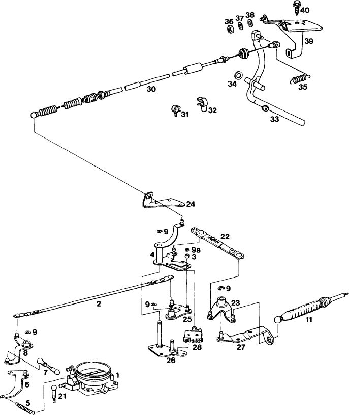
Length of connecting rod (B) from throttle valve housing to guide lever
|
75
|
||||
|
|
|||||
|
Length of connecting rod (2) from guide lever to slotted lever
|
345
|
||||
|
|
|||||
|
Length of connecting rod (10) above cylinder head cover (automatic transmission 722.1 (W 4 B 025) only)
|
306
|
||||
|
|
|||||
|
Adjustment
|
|||||
|
|
|||||
|
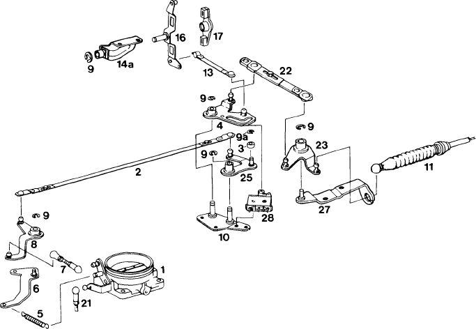
1 Check regulating linkage and Bowden wire for easy operation, distortion and absence of kinks. Replace individual parts, if required.
2 Disconnect connecting rod (B) on throttly valve housing. Check whether throttle valve rests against idle speed stop. Reconnect connecting rod free of tension and adjust to specified length, if required.
Note: Connecting rod (B) should be made of round material with screwed on ball sockets. Replace profilated sheet metal-connecting rod (A).
3 Adjust connecting rod (2) in such a manner that roller (3) in slotted lever (4) rests free of tension against final stop.
|
 |
||||
|
1074-7392
|
|||||
 |
|||||
|
|
|||||
|
The connecting rod can now be adjusted on one side only. Pay attention to installation position (refer to Fig.).
For installation date refer to section „A” Lefthand steering.
|
 |
||||
|
2 1st version 2a 2nd version
|
|||||
|
K57-10702
|
|||||
|
|
|||||
|
30.2 llb-300/7 F2
|
|||||
|
|
|||||
|
|
|||
|
Engines with decel shutoff
To guarantee operation of microswitch (3), the slotted lever (13) is provided with a restoring spring (arrow). As a result, the slotted lever will return reliably to end stop.
|
 |
||
|
|
|||
|
4 Vehicles with cruise control/Tempomat:
|
 |
||
|
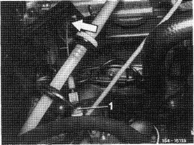
Tempomat, pneumatical
Check whether Bowden wire for cruise control/ Tempomat rests free of tension against regulating lever (arrow). Adjust with adjusting nut (1), if required.
|
|||
|
|
|||
|
Cruise control/Tempomat, electrical
Check whether actuator rests against idle speed stop of cruise control/Tempomat. For this purpose, disconnect pullrod (21) and push lever of actuator clockwise against idle speed stop.
When connecting pullrod (21), make sure that the lever of the actuator is lifted by approx. 1 mm from idle speed stop. Adjust pullrod, if required.
|
 |
||
|
|
|||
|
Checking full throttle stop
|
 |
||
|
Attention!
On vehicles with automatic transmission 722.3 (W 4 A 040) disconnect Bowden wire (11), reconnect after adjusting full throttle stop.
|
|||
|
|
|||
|
30.2 llb-300/8 F2
|
|||
|
|
|||
|
|
|||
|
5 With engine stopped, step on accelerator pedal from inside vehicle up to full throttle stop or on automatic transmission up to stop on kickdown switch. Throttle valve lever should rest against full throttle stop. If required, adjust regulating linkage with adjusting screw (arrow) in such a manner that the throttle valve lever rests against full throttle stop.
|
 |
||
|
|
|||
|
6 Vehicles with automatic transmission:
a) Adjust control pressure rod (11) with engine stopped. For this purpose, disconnect control pressure rod, push completely toward the rear against stop and reconnect free of tension. Adjust ball socket, if required.
|
 |
||
|
Control pressure rod with automatic transmission 722.1 (W 4 B 025)
|
|||
|
|
|||
|
b) Adjust Bowden wire (11) with engine stopped. For this purpose, disconnect connecting rod (22) and pull guide lever (23) in direction of arrow noticeably against idle speed stop on automatic transmission. Reconnect connecting rod (22) free of tension and adjust, if required.
|
 |
||
|
Bowden wire with automatic transmission 722.3 (W 4 A 080)
|
|||
|
|
|||
|
30.2 llb-300/9 F2
|
|||
|
|
|||
|
|
|||||||||||||||||||||||||||||||||||||||||||||||||||||||||||||||||||||||||||||||||||||||||||||||||||||||||||||||||||||||||||||||||||||||||||||||||||||||||||||||
|
Engine and chassis regulation Righthand steering model 123 Prior to September 1981
|
|||||||||||||||||||||||||||||||||||||||||||||||||||||||||||||||||||||||||||||||||||||||||||||||||||||||||||||||||||||||||||||||||||||||||||||||||||||||||||||||
|
|
|||||||||||||||||||||||||||||||||||||||||||||||||||||||||||||||||||||||||||||||||||||||||||||||||||||||||||||||||||||||||||||||||||||||||||||||||||||||||||||||
|
1072-7810/1
|
||||||||||||||||||||||||||||||||||||||||||||||||||||||||||||||||||||||||||||||||||||||||||||||||||||||||||||||||||||||||||||||||||||||||||||||||||||||||||||||
|
|
|||||||||||||||||||||||||||||||||||||||||||||||||||||||||||||||||||||||||||||||||||||||||||||||||||||||||||||||||||||||||||||||||||||||||||||||||||||||||||||||
|
30.2 llb—300/10 F2
|
|||||||||||||||||||||||||||||||||||||||||||||||||||||||||||||||||||||||||||||||||||||||||||||||||||||||||||||||||||||||||||||||||||||||||||||||||||||||||||||||
|
|
|||||||||||||||||||||||||||||||||||||||||||||||||||||||||||||||||||||||||||||||||||||||||||||||||||||||||||||||||||||||||||||||||||||||||||||||||||||||||||||||
|
|
||||||||||||||||||||||||||||||||||||||||||||||||||||||||||||||||||||||||||||||||||||||||||||||||||||||||||||||
|
Starting September 1981
|
||||||||||||||||||||||||||||||||||||||||||||||||||||||||||||||||||||||||||||||||||||||||||||||||||||||||||||||
|
|
||||||||||||||||||||||||||||||||||||||||||||||||||||||||||||||||||||||||||||||||||||||||||||||||||||||||||||||
|
1072-10646
|
||||||||||||||||||||||||||||||||||||||||||||||||||||||||||||||||||||||||||||||||||||||||||||||||||||||||||||||
|
|
||||||||||||||||||||||||||||||||||||||||||||||||||||||||||||||||||||||||||||||||||||||||||||||||||||||||||||||
|
||||||||||||||||||||||||||||||||||||||||||||||||||||||||||||||||||||||||||||||||||||||||||||||||||||||||||||||
|
|
||||||||||||||||||||||||||||||||||||||||||||||||||||||||||||||||||||||||||||||||||||||||||||||||||||||||||||||
|
30.2 llb-300/11 F2
|
||||||||||||||||||||||||||||||||||||||||||||||||||||||||||||||||||||||||||||||||||||||||||||||||||||||||||||||
|
|
||||||||||||||||||||||||||||||||||||||||||||||||||||||||||||||||||||||||||||||||||||||||||||||||||||||||||||||