General description of breakerless transistorized coil ignition system TSZ 4 and TSZ8u
|
|
|||
|
15-530 General description of breakerless transistorized coil ignition system TSZ 4 and TSZ8u
|
|||
|
|
|||
|
A.TSZ 4
|
|||
|
|
|||
|
Note
|
 |
||
|
This ignition system is widely free of maintenance requirements and guarantees adequate ignition voltage even at max. speeds and a more accurate adherence to firing point.
Identification: Yellow paint dot on housing top up to production date 930 and Bosch No. 0227 100 001.
|
|||
|
|
|||
|
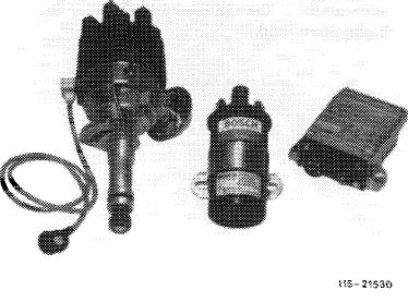
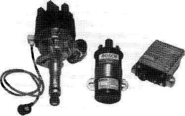
Components of ignition system
|
 |
||
|
Ignition coil
Design and external dimensions of the ignition coil are similar to those of a normal high-performance ignition coil. However, the coil layout is different. The transformation ratio amounts to approx. 1:185 as compared with 1:100 for conventional ignition coils.
Identification: blue paintwork and sticker Transistor Bosch No. 0 221 12201.
|
|||
|
|
|||
|
Pre-resistors (series resistors)
Pre-resistors 0.4 tt and 0.6 Q are similar to those of former ignition coil resistors: The resistance coil is surrounded by a ceramic body with projecting connections.
A sheet-metal clamp is placed around ceramic body for attachment. The color of this clamp provides information with regard to resistance value, which is also punched in as a number.
|
|||
|
|
|||
|
15.2 lib—530/1 F2
|
|||
|
|
|||
|
|
||||||
|
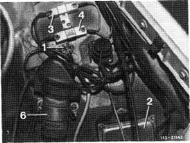
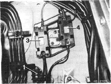
Model 126
1 Cable connector
2 Switching unit TSZ 4
3 Pre-resistor 0.6 ^2
4 Pre-resistor 0.4 i2 6 Ignition coil
|
 |
|||||
|
|
||||||
|
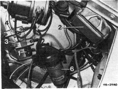
Model 123
1 Cable connector
2 Switching unit
3 Pre-resistor 0.6 i
4 Pre-resistor 0.4 ^ 6 Ignition coil
|
 |
|||||
|
|
||||||
|
Model 126
3 Covered pre-resistors
4 Covered pre-resistors
|
 |
|||||
|
|
||||||
|
Color
|
Code No.
|
Resistance
|
||||
|
|
||||||
|
Anodized, blue Anodized, metallic
|
0.4 0.6
|
0.4fi
o.6 n
|
||||
|
|
||||||
|
15.2 llb-530/2 F2
|
||||||
|
|
||||||
|
|
|||
|
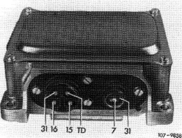
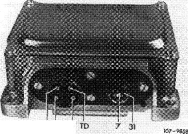
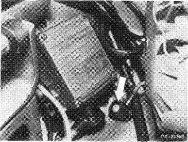
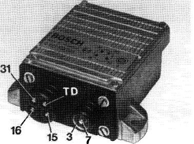
Switching unit
The switching unit contains several transistors, resistors and other electronic components in a metal housing. This metal housing protects the components against mechanical damage and splash water and serves also for eliminating dissipated electric heat. In the event of repairs, only the complete switching unit can be replaced.
|
31 16 15
|
||
|
|
|||
|
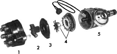
Ignition distributor
Instead of the contact breaker, the ignition distributor is provided with a transmitter section, which operates according to the induction principle. Ignition timing by centrifugal force and vacuum is similar to former ignition distributors.
|
|||
|
|
|||
|
1 Ignition distributor cap
2 Ignition distributor rotor
3 Shielding cap
4 Transmitter section
5 Ignition distributor housing
|
 |
||
|
115-10505
|
|||
|
|
|||
|
15.2 llb-530/3 F2
|
|||
|
|
|||
|
|
||||||||||||||||||||||||||||||||||||
|
Operation of transmitter section
|
||||||||||||||||||||||||||||||||||||
|
|
||||||||||||||||||||||||||||||||||||
|
A rotor with its number of teeth corresponding to number of engine cylinders produces during its rotation per tooth a change of magnetic flux in a magnetic field established by a permanent magnet. As a result, an induction coil located in magnetic field established a control voltage (0.3 V – 100 V) which depends in its size on engine speed, with a steep change from positive to negative half wave. This steep change of polarity of control voltage is used in switching unit following zero passage for impulse shaping, impulse amplification and interruption of primary current.
If the primary current is interrupted, the ignition voltage is induced in secondary winding of ignition coil. The dwell angle control in switching unit adapts the current flow time of primary current to the engine speed, that is, the dwell angle will also become larger with increasing speed, so that adequate ignition voltage is assured also in upper speed range.
|
||||||||||||||||||||||||||||||||||||
|
|
||||||||||||||||||||||||||||||||||||
 |
||||||||||||||||||||||||||||||||||||
|
|
||||||||||||||||||||||||||||||||||||
|
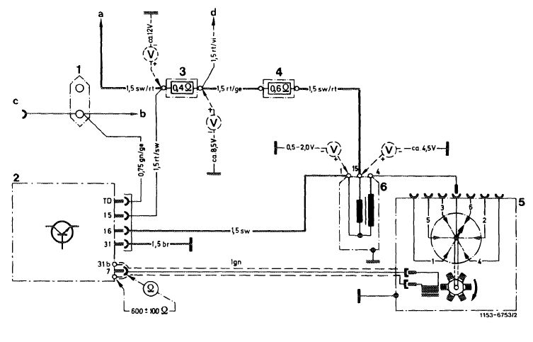
Wiring diagram breakerless transistorized ignition system TSZ 4
|
||||||||||||||||||||||||||||||||||||
|
|
||||||||||||||||||||||||||||||||||||
|
1 2-point cable connector
2 Switching unit
3 Pre-resistor 0.4 £2
4 Pre-resistor 0.6 fi
5 Ignition distributor with transmitter section
6 Ignition coil
|
a Ignition starter switch
b Instrument cluster, revolution
counter
c Diagnosis socket d Terminal 16 starter
|
|
||||||||||||||||||||||||||||||||||
|
|
||||||||||||||||||||||||||||||||||||
|
15.2 llb-530/4 F2
|
||||||||||||||||||||||||||||||||||||
|
|
||||||||||||||||||||||||||||||||||||
|
|
|||
|
B. TSZ 8 u
|
|||
|
|
|||
|
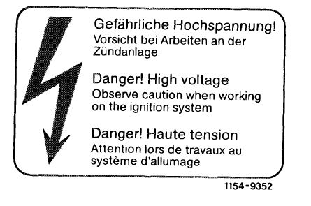
Notes concerning jobs on ignition system
|
|||
|
|
|||
|
Since model year 1981 national versions and standard version since September 1981, engines 110 are provided with the breakerless transistorized ignition system without rest potential and without pre-resistors TSZ 8 u. Compared with systems known up to now the output of this ignition system has been increased.
|
 |
||
|
|
|||
|
Prior to jobs at starting speed and jobs with ignition cables pulled off e. g. when testing compression pressure, switch off ignition and pull off plug (transmitter in ignition distributor) on switching unit (green cable) or attach protective plug ignition system, part No. 102 589 02 21 00 on diagnosis socket.
Prior to rotating engine — e. g. for testing pressure loss, adjust valve clearance — switch off ignition, pull off plug (transmitter in ignition distributor) on switching unit (green cable) or attach protective plug ignition system, part No. 102 589 02 21 00 to diagnosis socket.
|
 |
||
|
|
|||
|
Note concerning prevention of damage on ignition system
|
 |
||
|
• Do not connect e. g. a suppression capacitor or test lamp to terminal 1 of ignition coil.
• Do not short terminal 1 and 15 of ignition coil against ground (e. g. as a burglar alarm).
|
|||
|
|
|||
|
15.2 llb-530/5 F2
|
|||
|
|
|||
|
|
|||
|
• Do not disconnect battery with the engine running.
• Install only original components of ignition system (refer to components of ignition system).
Do not operate ignition system at starting speed without completely connected ignition harness.
• With the engine running, tests like, e. g., testing ignition cable 4 at a distance against ground (spark gap at starting speed) as well as pulling off of a spark plug connector are no longer permitted.
If insulation damage is suspected, evaluate scope pattern at idle speed and with driving position engaged.
• Testing of ignition voltage while starting with cable 4 pulled from ignition distributor is no longer permitted.
|
|||
|
|
|||
|
Components of ignition system
|
|||
|
|
|||
|
The ignition system comprises the ignition coil, the ignition distributor, the ignition harness and the switching unit:
|
 |
||
|
Ignition coil
The ignition coil is adapted to the TSZ switching unit and designed for a higher ignition performance.
|
|||
|
|
|||
|
i 15-21530
|
|||
|
|
|||
|
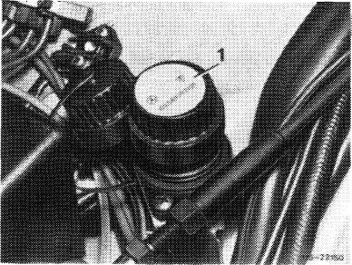
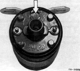
Different characteristics in relation to former ignition coils are:
1. The safety plug in cover of ignition coil (arrow).
2. A higher dome.
3. Cable connection to terminal 1 with thread M 5.
4. Cable connection to terminal 15 with thread M 6.
|
 |
||
|
|
|||
|
15.2 lib-530/6 F2
|
|||
|
|
|||
|
|
|||
|
The cover of ignition coil has an opening of 5.5 mm dia. which is closed with a plug. This plug will be released in the event of overpressure in switching unit caused by an intensive development of heat under influence of a defective final stage. To prevent uncontrolled release of plug or of sealing compound out of ignition coil, the ignition coil is provided with a protective cover.
|
51S-1SS3S
|
||
|
|
|||
|
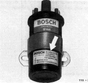
To prevent mixups, the ignition coil of the TSZ 8 u has a yellow information label (arrow) Bosch No. 0221 111 83 07.
Never replace ignition coil by one of the former ignition coils.
|
 |
||
|
|
|||
|
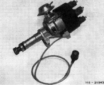
Ignition distributor
In principle, this ignition distributor with inductance transmitter corresponds with the version already known, except that its characteristic has been changed, together with a simplified vacuum control unit for ignition advance.
The line of the inductance transmitter from distributor to switching unit is a two-core line, it is insulated against ground and shielded.
The distributor rotor has an interference suppression resistor of 1 k£2 (code number R 1, on distributor rotor).
|
 |
||
|
|
|||
|
Ignition harness
The partially shielded spark plug connections and offset distributor plugs are designed to the higher ignition voltage.
An interference suppression resistor of 1 k!2 is installed in spark plug connectors.
They can be screwed off (thread M 4).
|
|||
|
|
|||
|
15.2 Mb—530/7 F2
|
|||
|
|
|||
|
|
|||
|
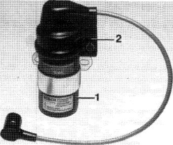
Switching unit
The switching unit is considerably smaller and lighter in weight. The housing has no vent bores. Connections are similar to the version already known.
This switching unit has been provided with new, special electronic components (control IC) with the following functions:
1. Limitation of primary current; there elimination of pre-resistors.
2. Dwell angle control at different battery voltage and engine speed, by max. primary current.
3. Cutout of rest potential; no primary current will flow with ignition switched on and engine stopped.
|
 |
||
|
115 -18941
|
|||
|
|
|||
|
Functional description
|
|||
|
|
|||
 |
|||
|
|
|||
|
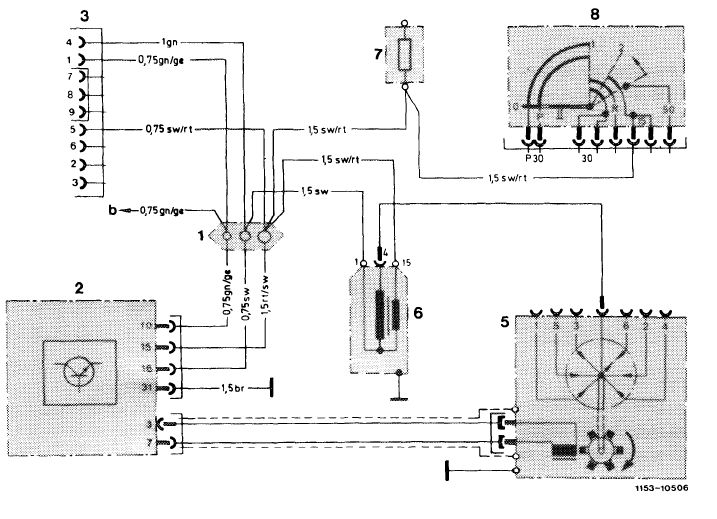
Wiring diagram breakerless transistorized ignition without pre-resistors TSZ 8 u
1 Line connector Color code
2 Switching unit br = brown
3 Diagnosis socket b To fuel pump relay ge = yellow
5 Ignition distributor with rpm limitation gr = green
6 Ignition coil rt = red
7 Fuse box terminal 15 sw = black
8 Ignition starter switch
|
|||
|
|
|||
|
15.2 llb-530/8 F2
|
|||
|
|
|||
|
|
|||
|
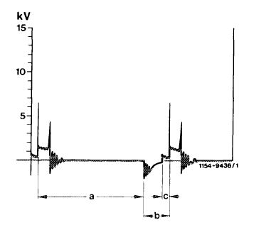
The max. primary current of the ignition coil is no longer determined by pre-resistors, but by a current limitation in switching unit. This current limitation is applied after the max. possible primary current has been attained.
The current limitation is indicated on oscilloscope at idle.
|
 |
||
|
kV Voltage
a Opening
b Dwell angle
c Current limitation
|
|||
|
|
|||
|
The optimal output of the ignition system is attained by the dwell angle control in switching unit. Within range of possible regulation, the dwell angle is regulated in such a manner that the same primary current will always be approximately attained in any operating condition, that is, at varying battery voltages and engine speeds.
|
|||
|
|
|||
|
With the engine stopped and the ignition switched on the primary current is switched off via switching unit (rest potential cutout). The primary current is switched on only in the event of a given impulse sequence from transmitter in ignition distributor.
The revolution counter in instrument cluster is connected to terminal TD.
|
|||
|
|
|||
|
15.2 Mb—530/9 F2
|
|||
|
|
|||