Coolant circuit and engine cooling
|
|
||||
|
20—005 Coolant circuit and engine cooling
|
||||
|
|
||||
|
Coolant circuit
|
 |
|||
|
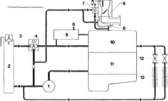
Coolant circuit for carburetor engine
|
||||
|
1203-7320
|
||||
|
|
||||
|
1 Coolant pump 8
2 Radiator 9
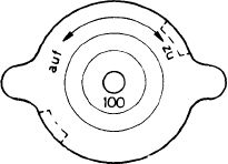
3 Radiator cap, code number 100 10
4 Thermostat 87 °C 11
5 Measuring sensor box 12
6 Temperature sensor for temperature gage 13
7 Automatic choke heating
|
Intake manifold heating
Carburetor
Cylinder head
Crankcase
Control cocks for car heating
Heat exchanger
|
|||
|
|
||||
|
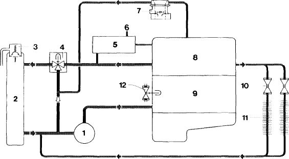
Coolant circuit for fuel injection engine
 |
||||
|
|
||||
|
1203-7319
|
||||
|
|
||||
|
1 Coolant pump 7
2 Radiator 8
3 Radiator cap, code number 100 9
4 Thermostat 87 °C 10
5 Measuring sensor box 11
6 Temperature sensor for temperature gage 12
|
Throttle housing pre-heating
Cylinder head
Crankcase
Control cocks for car heating
Heat exchanger
Warm-up throttle bypass valve
|
|||
|
|
||||
|
Note: The line for pre-heating the throttle housing (7) is omitted on engines with continuous fuel injection (CIS).
|
||||
|
|
||||
|
20.2-005/1 F3
|
||||
|
|
||||
|
|
|||
|
Engine cooling
|
ZIIS
|
||
|
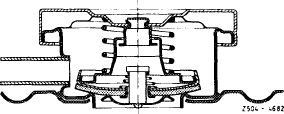
The spring-loaded radiator cap establishes a gauge pressure of approx. 1 bar in cooling system.
The factory fills the cooling system with an all year coolant, which consists of about 55% water and 45% antifreeze by volume.
This provides protection against freezing at temperatures down to —30°C and the additives in the antifreeze will prevent corrosion in the cooling system. Since the additives are subject to an aging process, the coolant must be replaced every two years.
To provide adequate protection against corrosion, the concentration of anti-freeze must offer protection against freezing of at least —20°C (30% by volume).
If an anti-freeze is not available and only water is filled, it is essential to add 1% of anti-corrosion oil (10 cc/liter water).
For the model 114 1 % or 10 cc/liter of anti-corrosion oil must be added even when using an anti-freeze to lubricate the heater cocks thoroughly.
The anti-freeze of the mixture filled at the factory will increase the boiling point, which is about 118°C for water at gauge a pressure of 1 bar, to approximately 125 °C.
The red mark on the temperature gauge begins at 122 (since the middle of may 1975, previously 115 °C).
This point deserves special attention, if only water with an anti-corrosion oil is used. Coolant could be thrown out, before the coolant temperature gauge needle reaches the red mark.
For full throttle, mountainous and caravan driving, high speed highway driving followed by traffic jams or when driving in areas with high outside temperatures, the coolant temperature gauge needle could move to the red mark when the anti-freeze protection is at least —30°C without throwing out coolant or having any engine trouble.
If the engine of a stationary car has to run for a long time, i.e. in traffic jams, it would be advantageous to move the selector lever of models with an automatic transmission to „N”. This will reduce the development of heat in the transmission and thus any additional heating of the coolant via the transmission oil cooler.
|
|||
 |
|||
|
|
|||
|
20.2-005/2 F3
|
|||
|
|
|||
|
|
||
|
An appropriately mixed coolant must be added when there is any loss of coolant through a leak in the cooling system or throwing out due to overheating.
The amount missing due to evaporation can be replaced with drinking water.
|
||
|
|
||
|
20.2-005/3
|
||
|
|
||