Checking idle speed stabilization on engines with refrigerant compressor
|
|
||||
|
07.3—145 Checking idle speed stabilization on engines with refrigerant compressor
|
||||
|
|
||||
|
Conventional tool
|
||||
|
|
||||
|
Voltmeter, revolution counter
|
||||
|
|
||||
|
Digital tester
|
e.g. made by Bosch, MOT 001.03
|
|||
|
|
||||
|
Testing
|
 |
|||
|
1 Run engine at idle. When adding refrigerant compressor, the idle engine speed should increase by approx. 80/min.
If the idle speed is not increasing, pull upper and lower vacuum line from switchover valve (43).
Vacuum should be available at upper line.
|
||||
|
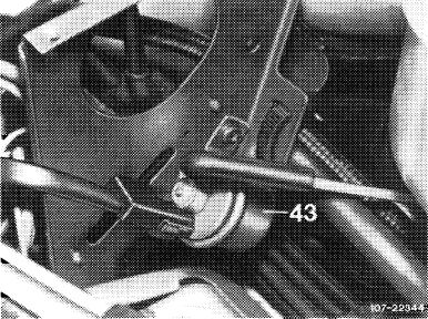
Model 107
43 Switchover valve (mounted on mounting bracket for coolant expansion tank).
|
||||
|
|
||||
|
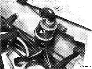
Layout switchover valves (43).
|
 |
|||
|
Model 1 23
|
||||
|
|
||||
|
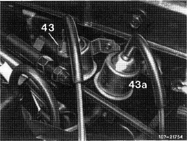
Model 126
43 Switchover valve air conditioning
(identification: green cap) 43a Switchover valve decel shutoff
(identification: gray cap)
|
 |
|||
|
|
||||
|
07.3.2 I la—145/1
|
F 2
|
|||
|
|
||||
|
|
|||||
 |
|||||
|
|
|||||
|
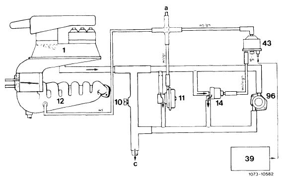
Function diagram idle speed stabilization on engines with refrigerant compressor 1 Mixture controller 43 Switchover valve rpm increase
10 Idle speed air screw air conditioning
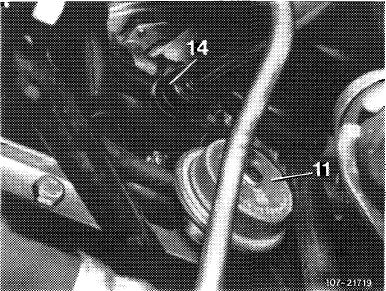
11 Decel circulating air valve 96 Supplementary air valve
14 Bypass valve air conditioning a Connection switchover valve
39 Relay air conditioning decel shutoff
c To idle speed air duct in intake manifold
|
Color code gn = green vi = purple ws = white
|
||||
|
|
|||||
|
Note: For operation decel shutoff and idle speed stabilization refer to 07.3—500.
|
|||||
|
|
|||||
|
2 Connect both vacuum lines with each other, idle speed should then increase by approx. 80/min. If not, renew bypass valve (14).
|
 |
||||
|
|
|||||
|
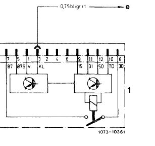
3 If the engine speed increases, check electric activation of switchover valve (43). For this purpose, pull off coupler: with refrigerant compressor switched on, battery voltage should be available. If voltage is available, replace switchover valve. If no voltage is available, test voltage supply according to wiring diagram (refer to wiring diagram group 83 Air conditioning system).
|
 |
||||
|
1 Fuel pump relay
e Refrigerant compressor
|
|||||
|
|
|||||
|
07.3.2 lla-145/2
|
F 2
|
||||
|
|
|||||