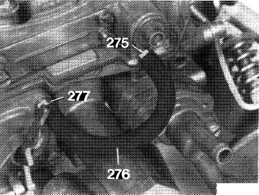
Subsequent installation of vapor bubble draw-off for accelerating pump (® 1975/76 only)
|
|
|||
|
07.2—156 Subsequent installation of vapor bubble draw-off for accelerating pump (® 1975/76 only)
|
|||
|
|
|||
|
A. General information and operation
|
|||
|
|
|||
|
Starting faults may come up at high outside temperatures as a result of vapor lock in accelerating pump.
As a remedy, a vapor bubble draw-off can be subsequently installed.
|
|||
|
|
|||
|
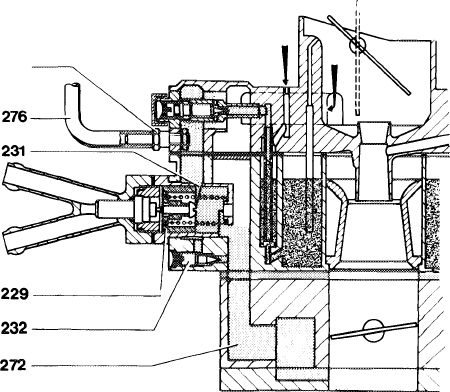
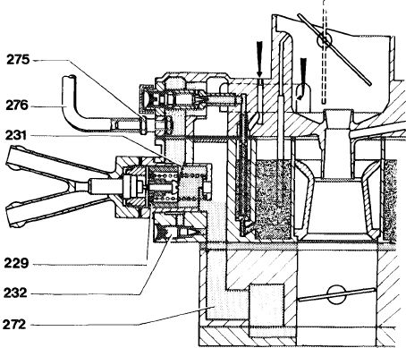
Layout of vapor bubble draw-off
|
 |
||
|
|
|||
|
Operation
|
|||
|
|
|||
|
At operating temperature, the control window (231) of thermostatically controlled bypass choke (TN choke) is closed. By means of leak air on control piston (229) at idle, the vacuum in intake pipe is effective up to pump chamber and able to draw-off any vapor bubbles there.
|
|||
|
|
|||
 |
|||
|
|
|||
|
1074-7172
|
|||
|
|
|||
|
07.2.2 la—156/1
|
|||
|
|
|||
|
|
|||
|
B. Subsequent installation
|
 |
||
|
1 Remove carburetor, remove carburetor cover and take out float (07.2-194).
2 Remove accelerating pump cover, diaphragm and diaphragm spring.
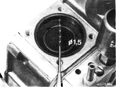
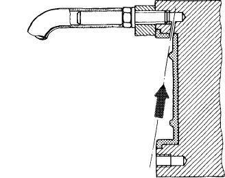
3 Drill a connecting duct of 1.5 mm dia. from pump chamber to threaded hole of cover fastening means.
|
|||
|
|
|||
|
Attention!
Be sure to maintain proper direction when drilling, to avoid drilling into float chamber. In addition, the suction and delivery bore in pump chamber must be kept closed (e.g. with grease) as a protection against drill chips.
|
 |
||
|
|
|||
|
107/1-7173
|
|||
|
|
|||
|
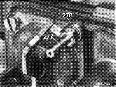
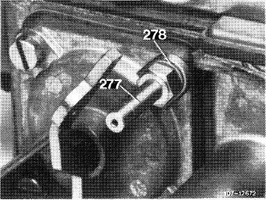
4 Clean connecting duct, pump chamber, suction and delivery bore (drill chips, grease). Install components of accelerating pump. Instead of fastening screw used up to now for threaded bore drilled through connecting duct, screw in draw-off connection (277) calibrated to 0.15 mm dia. together with sealing ring (278).
|
 |
||
|
|
|||
|
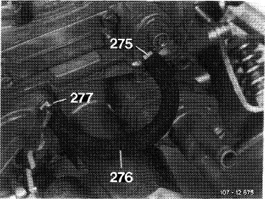
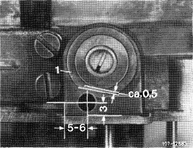
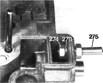
5 Drill fastening bore for draw-off connection (275).
For this purpose, refinish housing eye (1) in such a manner that approx. 0.5 mm material will remain on flange of carburetor cover. Mark bore, punch, drill to 2 mm dia. and then to 4 mm dia.
|
 |
||
|
|
|||
|
07.2.2 la-156/2
|
|||
|
|
|||
|
|
||||
|
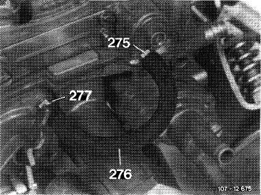
6 Screw draw-off connection (275) with sealing ring (278) and hex. nut (274) into carburetor cover.
Note: The flange of the draw-off connection should be seated flat. If required, refinish contact surface. If hex. nut on carburetor cover touches carburetor cover, file off slightly.
|
 |
1O7-1288S
|
||
|
|
||||
|
7 Shorten fuel hose (276) to 100 mm and plug on.
8 Insert float bracket and holddown, mount carburetor cover.
9 Install carburetor (07.2-194).
|
’?ln—1> U
|
|||
|
|
||||
|
C. Checking vapor bubble draw-off for function
|
 |
|||
|
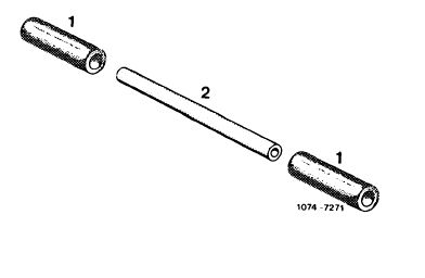
Test line
1 Vacuum hose, 30 mm long
2 Transparent vacuum line, 65 mm long
|
||||
|
|
||||
|
1 Run engine at operating temperature for a short moment and stop. Remove fuel hose and actuate throttle valve lever smoothly several times. A fuel jet should now come out of draw-off connection (277). If not, the throttle bore in draw-off connection is clogged. Clean throttle bore, if required.
|
 |
|||
|
|
||||
|
07.2.2 la-156/3
|
||||
|
|
||||
|
|
|||
|
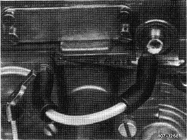
2 Plug-on self-made test line, run engine at idle. Fuel or vapor bubbles should be drawn off, visible in transparent test line.
|
 |
||
|
Test line
|
|||
|
|
|||
|
3 If neither fuel nor vapor bubbles are drawn off, check draw-off connection (275) for passage and clean, if required.
|
 |
||
|
|
|||
|
4 If there is still no draw-off, there is no or not enough vacuum available. In this case, unscrew leak air adjusting screw (232) by one turn. Repeat test.
5 Pull off test line and plug-on fuel hose (276).
6 Set to idle (07.2-100).
Attention!
When adjusting or checking idle speed emission value, the fuel hose (276) for drawing off at accelerating pump must be pulled off.
275
|
|||
|
|
|||
|
1074-7172
|
|||
|
|
|||
|
07.2.2 la-156/4
|
|||
|
|
|||
|
|
|||||
|
Flat rate
Basic job: 19 work units or 1.6 hours Related job: 16 work units or 1.3 hours
Spare parts
|
|||||
|
|
|||||
|
Designation
|
Part no.
|
||||
|
|
|||||
|
Conversion set for vapor bubble draw-off of accelerating pump
|
110 586 00 07
|
||||
|
|
|||||
|
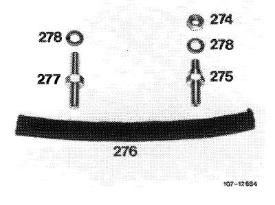
Conversion set
274 Hex nut.
275 Draw-off connection
276 Fuel hose
277 Draw-off connection with 0.15 mm throttle bore (orifice)
278 Sealing ring
|
 |
||||
|
|
|||||
|
07.2.2 la-156/5
|
|||||
|
|
|||||
