Subsequent installation of modified adjusting pin for air valve preload of stage II
|
|
||||
|
07.2-175 Subsequent installation of modified adjusting pin for air valve preload of stage II
|
||||
|
|
||||
|
Testing and adjusting values
|
||||
|
|
||||
|
National version
|
Adjusting weight
|
Length1)
|
||
|
|
||||
|
1976
|
170 + 2
|
190
|
||
|
|
||||
|
1976
|
160 ±2
|
180
|
||
|
|
||||
|
Federal 1973/74
|
112 ± 2
|
125
|
||
|
|
||||
|
California 1974
|
143 + 2
|
160
|
||
|
|
||||
|
Federal and California 1975/76
|
170 ±2
|
190
|
||
|
|
||||
|
M These dimensions apply to St 37. When using other materials, the specified testing weight must be maintained. The respective length results from this weight.
|
||||
|
|
||||
|
Air valve gap
|
||||
|
|
||||
|
When loaded with adjusting weight
|
1.5 mm
|
|||
|
|
||||
|
Conventional tools
|
||||
|
|
||||
|
Hex. socket wrench 2.5 mm
|
||||
|
|
||||
|
Drill 4.6 mm dia.
|
||||
|
|
||||
|
Self-made tool
|
||||
|
|
||||
|
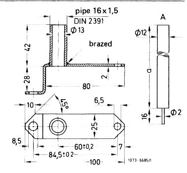
Adjusting device for air valve of stage II
|
 |
|||
|
|
||||
|
07.2.2 la—175/1
|
||||
|
|
||||
|
|
|||
|
Subsequent installation
|
|||
|
|
|||
|
1 Remove carburetor cover (07.2—192).
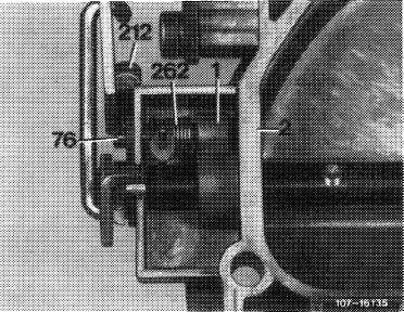
2 Unscrew locking screw (212), remove adjusting pin (76) and restoring spring of adjusting pin.
|
|||
|
|
|||
|
3 Clamp carburetor cover into vise, using projective jaws.
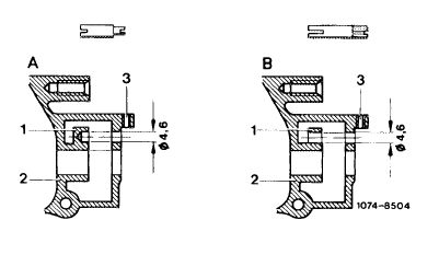
4 Extend rear mounting bore of adjusting pin. For this purpose, drill completely through housing eye (1) with a drill of 4.6 mm dia.
|
 |
||
|
A Before B New
|
|||
|
|
|||
|
Attention!
Do not damage carburetor housing wall (2) toward mixing chamber while drilling.
|
|||
|
|
|||
|
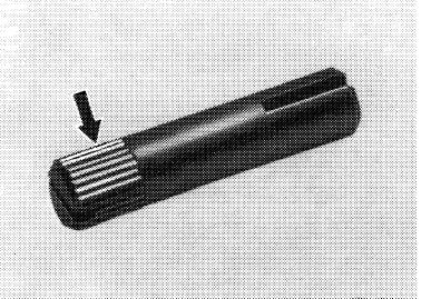
5 Install new adjusting pin with knurls and restoring spring with slide block. For this purpose, move restoring spring into installation position. Slip-in adjusting pin up to stop while turning adjusting pin.so that the restoring spring can engage in slot of driver. Install carburetor cover.
6 Complete air valve adjustment of stage II (07.2-170).
|
 |
||
|
1 Housing eye
2 Carburetor housing wall 76 Adjusting pin
212 Locking screw
262 Restoring spring
|
|||
|
|
|||
|
New adjusting pin with knurls (arrow)
|
 |
||
|
|
|||
|
07.2.2 la-175/2
|
|||
|
|
|||