Synchronizing idle speed systems
|
|
|||||
|
07.2—101 Synchronizing idle speed systems
|
|||||
|
|
|||||
|
Identification: Information plate in national language on cross member in front of radiator or on cylinder head cover. Adjust engines according to data of respective emission control information plate.
|
|||||
|
|
|||||
|
Testing and adjusting values
|
|||||
|
|
|||||
|
National version
|
Idle speed 1/min
|
Idle speed emission value % CO
|
|||
|
|
|||||
|
up to 1976
|
max. 1.5
|
||||
|
|
|||||
|
1976
|
800-900
|
||||
|
|
|||||
|
max. 1.0 without air injection
|
|||||
|
|
|||||
|
1976
|
|||||
|
|
|||||
|
1973
|
|||||
|
|
|||||
|
750-900
|
up to 1.5
|
||||
|
|
|||||
|
1974 Federal
|
|||||
|
|
|||||
|
1974 California
|
700-900
|
6—8 without air injection
|
|||
|
|
|||||
|
1975/76
|
800-900
|
max. 1.0 without air injection
|
|||
|
|
|||||
|
Special tools
|
|||||
|
|
|||||
|
Oil telethermometer
|
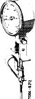 |
116 589 27 21 00
|
|||
|
|
|||||
|
Digital tester
|
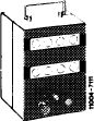 |
001 589 54 21 00
|
|||
|
|
|||||
|
Connecting cable
|
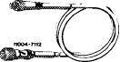 |
000 589 04 90 00
|
|||
|
|
|||||
|
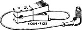
Intermediate plug (adaptor)
|
(WC .IE
|
000 589 72 63 00
|
|||
|
|
|||||
|
Trigger
|
 |
000 589 71 63 00
|
|||
|
|
|||||
|
07.2.2 la-101/1
|
|||||
|
|
|||||
|
|
|||
|
Conventional tools
|
|||
|
|
|||
|
Rpm and CO measuring instrument
|
|||
|
|
|||
|
Synchronizing
|
 |
||
|
1 Connect test instruments. Run engine oil temperature to 60-80 °C.
2 Remove air filter.
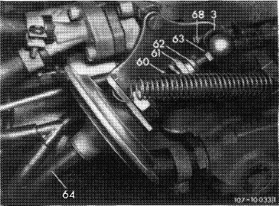
3 Check idle speed and adjust with adjusting screw (68), if required.
|
|||
|
|
|||
|
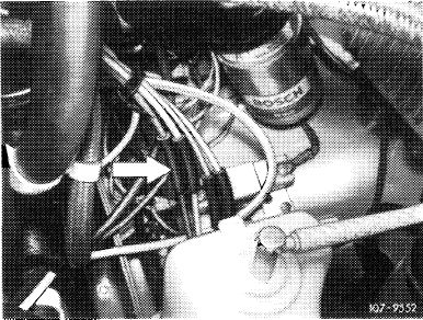
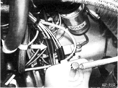
4 Check idle speed emission value without air injection. For this purpose, make air injection inoperative as follows (for (usa) 1973/74 nothing need be made inoperative):
|
 |
||
|
© 1976
Pull off blue/purple vacuum line at connecting point (arrow).
|
|||
|
|
|||
|
1976, model 114
|
 |
||
|
Pull rubber cap (arrow) from blue/purple vacuum line.
|
|||
|
|
|||
|
07.2.2 la—101/2
|
|||
|
|
|||
|
|
|||
|
T) 1976, model 116
|
 |
||
|
Pull rubber cap (arrow) from blue/purple vacuum line.
|
|||
|
|
|||
|
(usa) California 1974
Pull off red vacuum line at connecting point (arrow). (@) 1975/76
Pull off blue/purple vacuum line at connecting point (arrow).
|
 |
||
|
|
|||
|
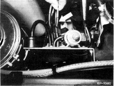
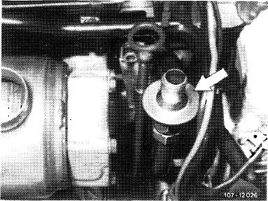
The exhaust gas for idle speed CO measurement on vehicles with catalyst, C-D1976 and <©> 1975/76, is drawn off in front of catalyst at check valve (arrow) of air injection.
|
 |
||
|
|
|||
|
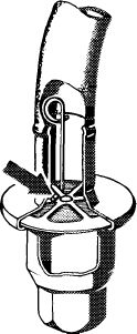
For measuring idle speed emissions, open valve plate of check valve by means of a self-made wire hook. Connect exhaust gas hose of CO measuring instrument to check valve.
|
 |
||
|
|
|||
|
1074-6964
|
|||
|
|
|||
|
07.2.2 la—101/3
|
|||
|
|
|||
|
|
|||
|
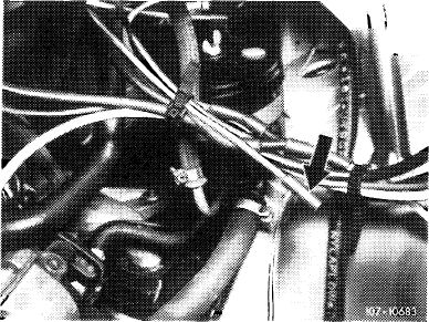
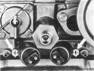
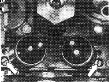
5 Adjust idle speed emission value without air injection. For this purpose, adjust both adjusting screws (arrows) uniformly.
Screwing out = richer Screwing in = leaner
Accelerate for a short moment, check idle speed and idle speed emission value once again and readjust, if required.
|
 |
||
|
|
|||
|
6 Check for uniform adjustment (synchronization) of mixture adjusting screws (arrows).
|
 |
||
|
|
|||
|
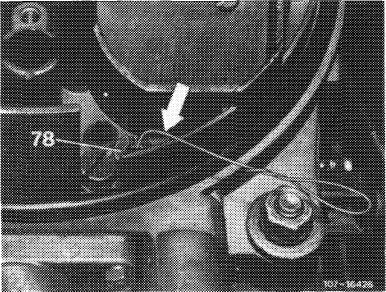
For this purpose, insert test wire of 0.5 mm dia. (arrow) into both air correction nozzles (78) one after the other and measure CO increase. CO increase should be uniformly high on both sides. Readjust with mixture adjusting screws, if required.
Note: To prevent measuring faults, do not insert test wire deeper than 10 mm into idle speed jet. Without test wire the max. idle speed emission value must not be exceeded.
|
 |
||
|
|
|||
|
Then check whether the max. permissible idle speed emission value is not exceeded without test wire and uniformly adjust both mixture adjusting screws, if required.
7 Reattach vacuum hose for air injection (air injection operating). The idle speed emission value should now be below the previously set value.
|
|||
|
|
|||
|
07.2.2 la-101/4
|
|||
|
|
|||