Removal and installation of choke
|
|
|||
|
07.2—140 Removal and installation of choke
|
|||
|
|
|||
|
Note
|
|||
|
|
|||
|
The starter housing can be removed or installed without difficulties only with carburetor removed.
|
|||
|
|
|||
|
Removal
|
 |
||
|
1 Remove carburetor (07.2-194).
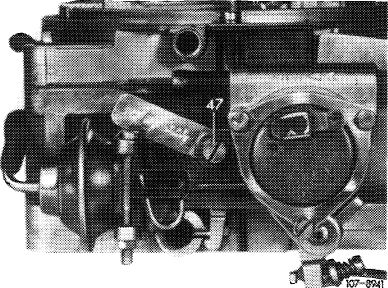
2 Pull vacuum hose from choke housing. Unscrew fastening screw, remove choke housing and choke cover.
|
|||
|
Choke housing version 1 (sheet metal pulldown)
|
|||
|
|
|||
|
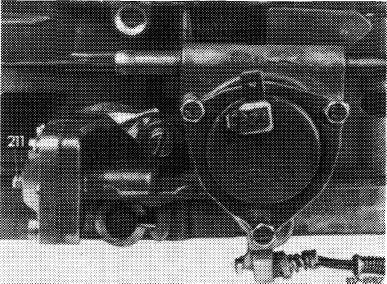
Starting May 1973 a cast iron choke housing with integrated pulldown and a modified fast idle cam is installed. The choke valve gap is set by means of adjusting screw (211) to simplify adjustment. Subsequent installation is generally possible.
|
 |
||
|
Choke housing version 2 (cast iron choke housing)
|
|||
|
|
|||
|
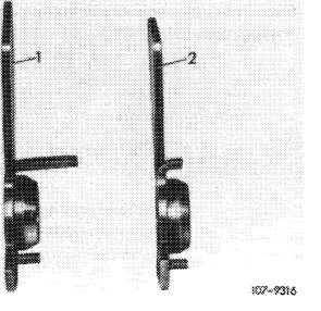
Fast idle cam versions
1 For choke housing with sheet metal pulldown
2 For cast iron choke housing (with short driver)
|
 |
||
|
|
|||
|
07.2.2 la-140/1
|
|||
|
|
|||
|
|
||||
|
Installation
|
 |
|||
|
3 For installation, set up carburetor in such a manner that the choke housing can be installed vertically.
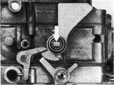
4 Position fast idle cam as shown in illustration and align.
5 Align driver lever for choke rod by means of a screwdriver inserted through bore in carburetor housing (arrow) in such a manner that the recess in driver lever shows up horizontally in center of carburetor housing bore.
|
||||
|
|
||||
|
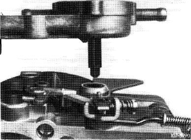
6 Carefully install choke housing from above.
|
 |
|||
|
|
||||
|
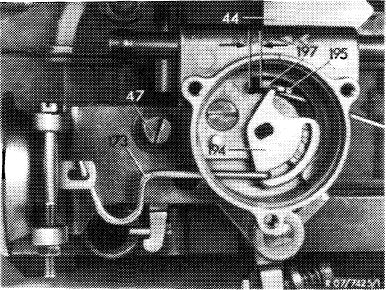
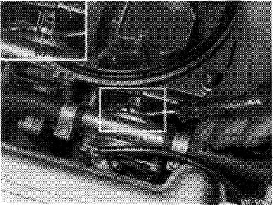
7 Check that drivers (196 and 197) are aligned as shown in illustration.
8 Check whether the driver (196 or 194) is moving when the choke valve is actuated, e.g. that it is positively connected. Then attach choke housing.
|
 |
|||
|
Choke housing version 1 (sheet metal pulldown)
44 Fast idle cam 194
47 Fastening screw 173 Connecting rod 197
|
Driver for actuating fast
idle cam
Driver of fast idle cam
|
|||
|
|
||||
|
Attention!
When installing a new choke housing, apply choke housing mark (07.2-142).
|
 |
|||
|
Choke housing version 2 (cast iron choke housing)
44 Fast idle cam
196 Driver for actuating fast idle cam
197 Driver of fast idle cam
|
||||
|
|
||||
|
07.2.2 la-140/2
|
||||
|
|
||||
|
|
||||
|
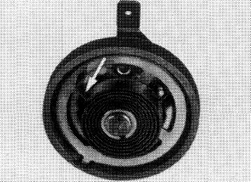
9 Install choke cover, making sure that the driver in choke housing rests against bimetallic spring side (arrow).
|
 |
|||
|
Spare parts for installing cast iron choke housing
|
||||
|
Designation
|
Part no.
|
|||
|
Choke housing Fast idle cam Fastening screw
|
000 070 19 47 110071 1262
001 071 27 71
|
|||
|
|
||||
|
07.2.2 la-140/3
|
||||
|
|
||||