Removal and installation of carburetor
|
|
|||||
|
07.2—194 Removal and installation of carburetor
|
|||||
|
|
|||||
|
Identification: Information plate in national language on cross member in front of radiator or on cylinder head cover. Adjust engines according to data of respective exhaust gas information plate.
|
|||||
|
|
|||||
|
Testing and adjusting values
|
|||||
|
|
|||||
|
Idle speed adjustment
|
|||||
|
|
|||||
|
National version
|
Idle speed 1/min
|
Idle speed emission value % CO
|
|||
|
|
|||||
|
up to 1976
|
max. 1.5
|
||||
|
|
|||||
|
1976
|
800-900
|
||||
|
|
|||||
|
max. 1.0 without air injection
|
|||||
|
|
|||||
|
T) 1976
|
|||||
|
|
|||||
|
<psi> 1973
|
|||||
|
|
|||||
|
750-900
|
up to 1.5
|
||||
|
|
|||||
|
1974 Federal
|
|||||
|
|
|||||
|
1974 California
|
700-900
|
6—8 without air injection
|
|||
|
|
|||||
|
1975/76
|
800-900
|
max. 1.0 without air injection
|
|||
|
|
|||||
|
Vacuum governor1)
|
|||||
|
|
|||||
|
National version
|
Engine speed
Vacuum hose pulled off
1/min
|
Engine speed
Driving position engaged
1/min
|
|||
|
|
|||||
|
without
TN choke
|
with
TN choke
|
||||
|
|
|||||
|
1976
|
|||||
|
|
|||||
|
1976
|
|||||
|
|
|||||
|
1700-1900
|
600-700
|
||||
|
|
|||||
|
1973/74
|
1200-1400
|
||||
|
|
|||||
|
1975/76
|
|||||
|
|
|||||
|
l) When engaging all auxiliary units, the engine should still run smoothly.
|
|||||
|
|
|||||
|
07.2.2 la—194/1
|
|||||
|
|
|||||
|
|
|||||||
|
Tightening torques
|
Nm
|
(kpm)
|
|||||
|
|
|||||||
|
with new insulating flange
|
10
|
(1.0)
|
|||||
|
|
|||||||
|
Carburetor fastening nuts
|
|||||||
|
|
|||||||
|
with insulating flange used up to now
|
8
|
(0.8)
|
|||||
|
|
|||||||
|
Special tools
|
|||||||
|
|
|||||||
|
f ■
|
 |
||||||
|
|
|||||||
|
Oil telethermometer
|
I
|
116 589 27 21 00
|
|||||
|
|
|||||||
|
Digital tester
|
 |
001 589 54 21 00
|
|||||
|
|
|||||||
|
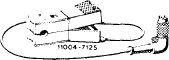
Connecting cable 6 m long
|
000 589 04 90 00
|
||||||
|
|
|||||||
|
I1OO4-T112 \
|
|||||||
|
|
|||||||
|
Intermediate plug (adaptor)
|
000 589 72 63 00
|
||||||
|
|
|||||||
|
Trigger
|
 |
000 589 71 63 00
|
|||||
|
|
|||||||
|
Torque wrench 4—16 Nm (40—160 kpcm)
|
 |
000 589 67 21 00
|
|||||
|
|
|||||||
|
Conventional tools
|
|||||||
|
|
|||||||
|
Revolution counter, CO measuring instrument
|
|||||||
|
|
|||||||
|
07.2.2 la-194/2
|
|||||||
|
|
|||||||
|
|
|||
|
Removal
|
 |
||
|
1 Remove air filter.
2 Evacuate excess pressure in cooling system by loosening radiator cap for a short moment, then tighten cap again.
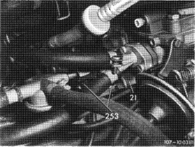
3 Unscrew fuel return valve. Pull off electric cable on choke cover, plug on idle speed shutoff valves, vacuum lines and coolant hoses. Disconnect regulating rod on carburetor.
|
|||
|
|
|||
|
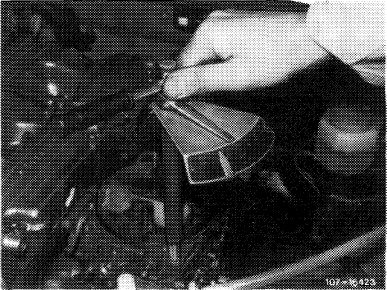
4 Unscrew carburetor fastening nuts and remove carburetor.
|
|||
|
|
|||
|
Installation
|
|||
|
|
|||
|
5 Install carburetor in vice versa sequence. Proceed as follows:
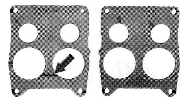
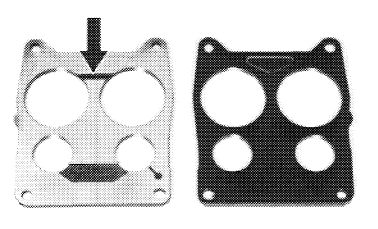
• Check insulating flange for damage and replace, if required.
• Pay attention to installation position and various insulating flange versions.
|
|||
|
|
|||
|
(@) 1973/74
(@) California 1974
Arrow = groove for drawing off fuel evaporation vapors, should point toward carburetor.
|
 |
||
|
|
|||
|
CD 1976 (D 1976 (usa) 1975/76
Arrow = groove for drawing off fuel and crankcase evaporation vapors, should point toward carburetor.
Attention!
This insulating flange should no longer be installed for model years 1973/74.
|
 |
||
|
|
|||
|
107-9854/1
|
|||
|
|
|||
|
07.2.2 la-194/3
|
|||
|
|
|||
|
|
|||||
|
• Tighten carburetor fastening nuts uniformly and crosswise to specified torque.
Attention!
To prevent distortion of carburetor, tighten with a torque wrench only and up to specified torque.
|
 |
||||
|
|
|||||
|
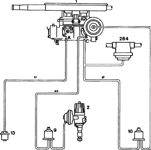
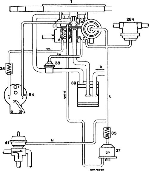
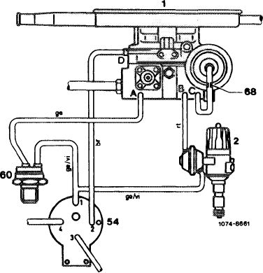
Attach vacuum lines on carburetor according to diagram.
|
|||||
|
|
|||||
|
1973/74 Federal
|
 |
||||
|
A Vacuum connection for vacuum switch
(13) of ignition retard B Vacuum connection for switchover valve
(9) of ignition retard
C Vacuum connection for switchover valve
(10) of throttle valve lift by vacuum governor, as well as for fuel return valve (284)
Line colors
gr = grey bl = blue ws = white
|
|||||
|
ws
|
1073-8659
|
||||
|
|
|||||
|
07.2.2 la-194/4
|
|||||
|
|
|||||
|
|
||||
|
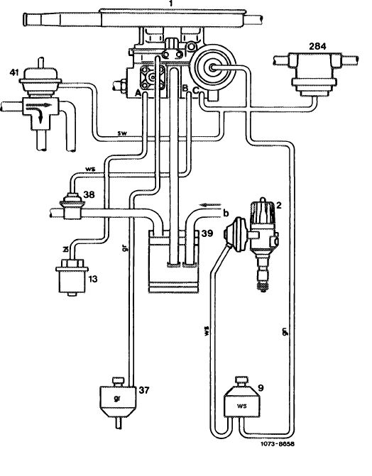
1974 California
|
 |
|||
|
A Vacuum connection for vacuum switch (13)
of ignition adjustment B Vacuum connection for draw-off valve (38)
of fuel evaporation control system C Vacuum connection for switchover valve (9)
of ignition adjustment, decel diverter valve
of air injection, vacuum governor and fuel
return valve (284)
Line colors
bl = blue
br = brown
gr = grey
gn = green
rt = red
ws = white
|
||||
|
|
||||
|
1975/76,
|
||||
|
|
||||
|
A Vacuum connection check valve (35) of
vacuum booster for EGR B Vacuum connection for draw-off valve (38)
of fuel evaporation control system C Vacuum connection for check valve (35) of
float chamber vent system, vacuum governor
and fuel return valve (284)
Line colors
|
 |
|||
|
bl = br =
|
blue brown
|
|||
|
gn = green
sw = black
vi = purple
ws = white
|
||||
|
|
||||
|
07.2.2 la-194/5
|
||||
|
|
||||
|
|
||||
|
1976
|
 |
|||
|
A Vacuum connection 40 °C thermovalve (60) of EGR
B Vacuum connection for ignition advance
C Vacuum connection for vacuum governor
D Vacuum connection for vacuum booster (54) of EGR
Line colors
|
||||
|
br
ge
rt vi
|
brown yellow red purple
|
|||
|
|
||||
|
6 Adjust idle speed (07.2-100).
|
||||
|
|
||||
|
07.2.2 la-194/6
|
||||
|
|
||||