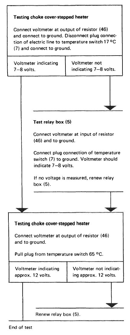
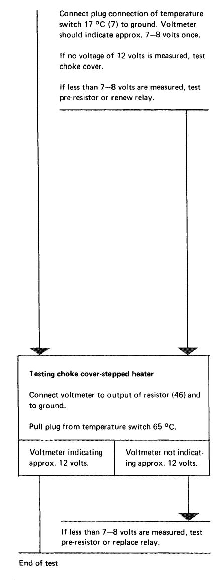
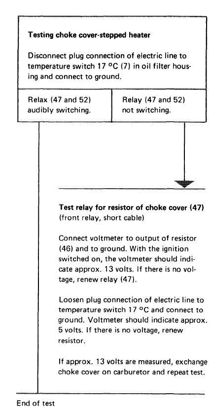
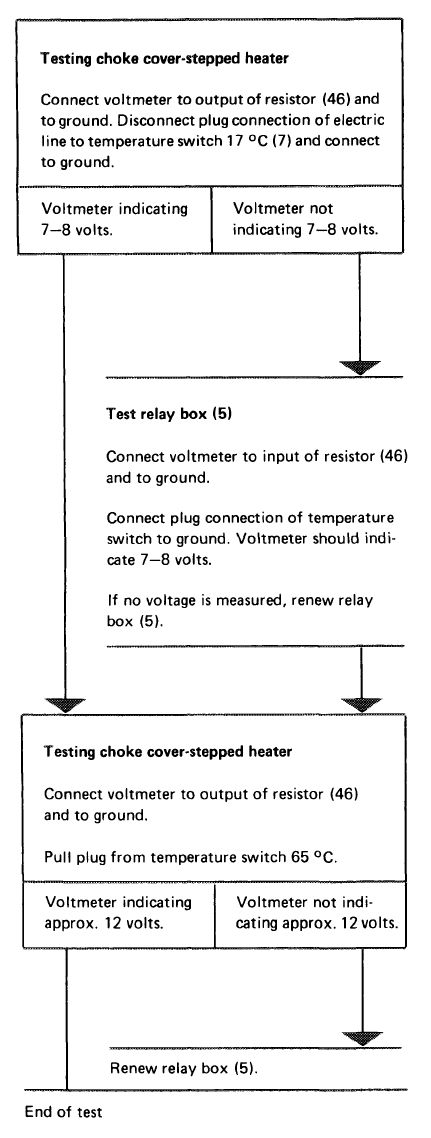
Checking choke cover-stepped heater
|
|
||||||
|
07.2—145 Checking choke cover-stepped heater
|
||||||
|
|
||||||
|
A. ©1976
|
||||||
|
|
||||||
|
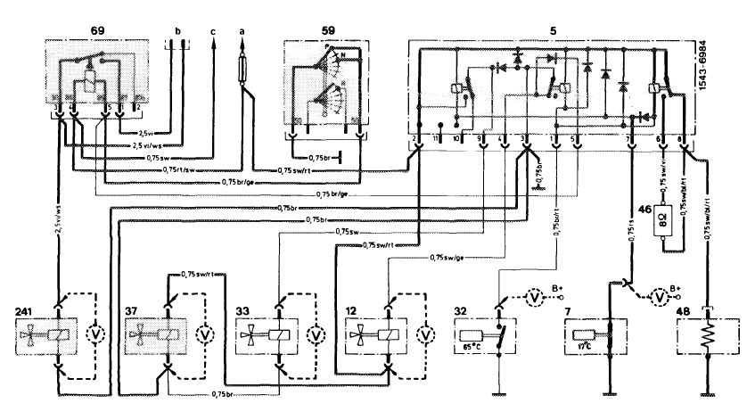
Test conditions:
|
All fuses in order, engine at operating temperature, run engine at idle.
|
|||||
|
|
||||||
|
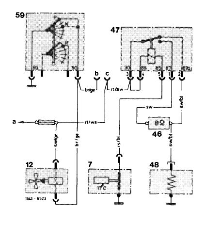
Wiring diagram (drawn with ignition switched off below 17 °C engine oil temperature)
|
||||||
|
|
||||||
|
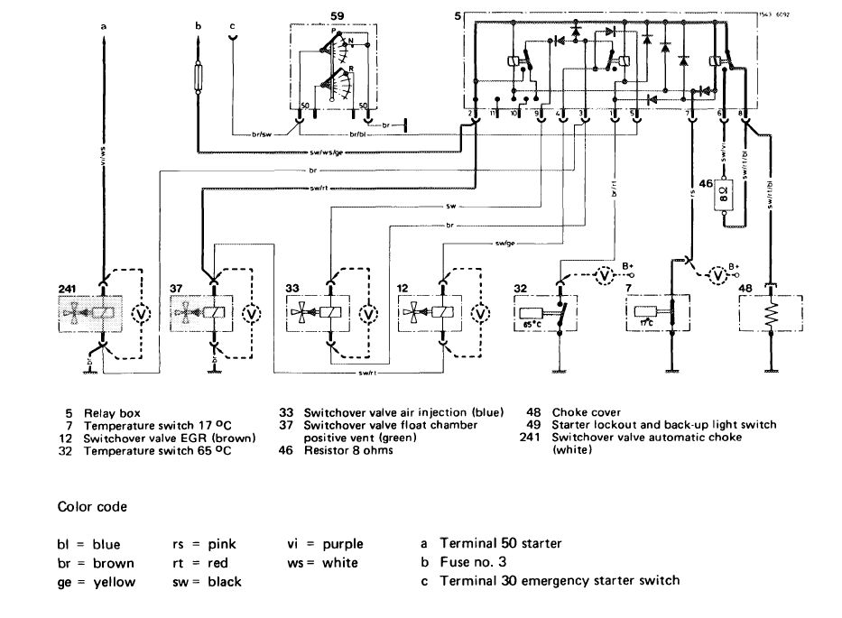
Choke cover-stepped heater, automatic choke, positive and negative venting of float chamber
|
||||||
|
|
||||||
 |
||||||
|
|
||||||
|
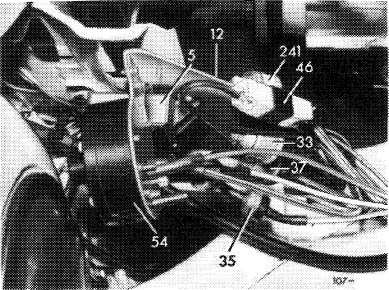
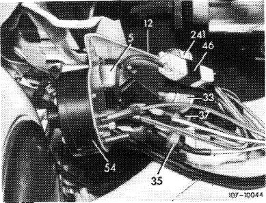
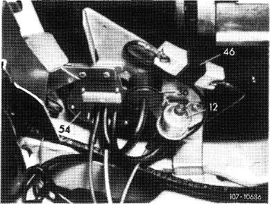
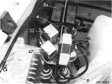
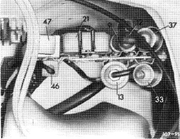
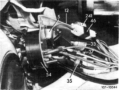
5 Relay box
7 Temperature switch 17 °C
12 Switchover valve EGR (brown)
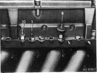
32 Temperature switch 65 °C
|
33 Switchover valve air injection (blue) 37 Switchover valve float chamber
positive ventilation (green) 46 Resistor 8 ohms
|
48 Choke cover
59 Starter lockout and back-up lamp switch 241 Switchover valve automatic choke (white)
|
||||
|
|
||||||
|
Color code
|
||||||
|
|
||||||
|
bl = blue br = brown ge = yellow
|
rs = pink rt = red sw= black
|
vi = purple ws= white
|
a Fuse no. 4
b Coupler to main conductor
Cable color purple — starter terminal 50 Cable color purple/white — starter switch terminal 50
c Warning switch catalyst temperature
|
|||
|
|
||||||
|
07.2.2 la-145/1
|
||||||
|
|
||||||
|
|
|||
 |
 |
||
 |
|||
 |
|||
 |
|||
|
|
|||
|
07.2.2 la-145/2
|
|||
|
|
|||
|
|
|||||||||||||||||||||||||||||||||||||||||
|
B. ©1976
|
|||||||||||||||||||||||||||||||||||||||||
|
|
|||||||||||||||||||||||||||||||||||||||||
|
Test conditions:
|
All fuses in order, engine at operating temperature, run engine at idle.
|
||||||||||||||||||||||||||||||||||||||||
|
|
|||||||||||||||||||||||||||||||||||||||||
|
Wiring diagram (drawn with ignition switched off, below 17 °C engine oil temperature)
|
|||||||||||||||||||||||||||||||||||||||||
|
|
|||||||||||||||||||||||||||||||||||||||||
|
Choke cover-stepped heater, EGR
|
|||||||||||||||||||||||||||||||||||||||||
|
|
|||||||||||||||||||||||||||||||||||||||||
|
Color code
bl = blue br = brown ge = yellow
|
rs = pink rt = red sw= black
|
vi = purple ws= white
|
 |
||||||||||||||||||||||||||||||||||||||
|
a Fuse no. 3 (15/54)
b Relay starter terminal 85
c Relay starter terminal 86
|
|||||||||||||||||||||||||||||||||||||||||
|
7 Temperature switch 17 °C
12 Switchover valve EGR (brown)
46 Pre-resistor 8 ohms
47 Relay pre-resistor choke cover
48 Choke cover
49 Starter lockout and back-up light switch
|
|||||||||||||||||||||||||||||||||||||||||
|
|
|||||||||||||||||||||||||||||||||||||||||
|
 |
||||||||||||||||||||||||||||||||||||||||
|
|
|||||||||||||||||||||||||||||||||||||||||
|
07.2.2 la-145/3
|
|||||||||||||||||||||||||||||||||||||||||
|
|
|||||||||||||||||||||||||||||||||||||||||
|
|
|||
 |
 |
||
|
|
|||
|
07.2.2 la-145/4
|
|||
|
|
|||
|
|
|||
|
C. ©1973/74
|
|||
|
|
|||
|
Test conditions:
|
All fuses in order, engine at operating temperature, run engine at idle.
|
||
|
|
|||
|
Wiring diagram (drawn with ignition switched off, below 17 °C engine oil temperature)
|
|||
|
|
|||
|
Choke cover-stepped heater, throttle valve lift
|
|||
|
|
|||
 |
|||
|
|
|||
|
07.2.2 la-145/5
|
|||
|
|
|||
|
|
|||
 |
 |
||
 |
|||
|
|
|||
|
07.2.2 la-145/6
|
|||
|
|
|||
|
|
||||||
|
D. @> 1974 California
|
||||||
|
|
||||||
|
Test conditions:
|
All fuses in order, engine at operating temperature, run engine at idle.
|
|||||
|
|
||||||
|
Wiring diagram (drawn with ignition switched off, below 17 °C engine oil temperature)
|
||||||
|
|
||||||
|
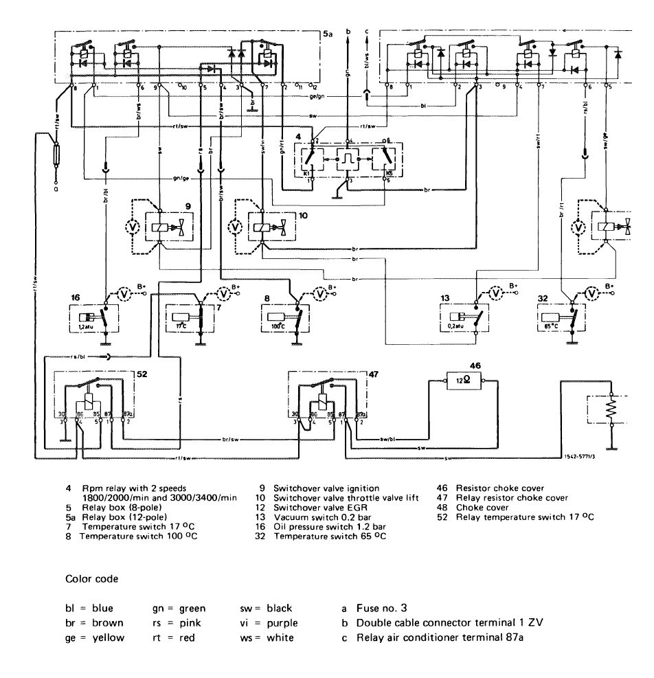
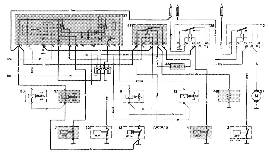
Choke cover-stepped heater, fuel evaporation control system
|
||||||
|
|
||||||
 |
||||||
|
|
||||||
|
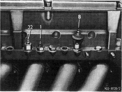
3 Temperature switch 62 °C
7 Temperature switch 17 °C
8 Temperature switch 100 °C
9 Switchover valve ignition
12 Switchover valve EGR
13 Vacuum switch
|
21 Switchbox
25 Relay disconnection temperature switch 62 °C/100 °C
26 Relay auxiliary fan
27 Auxiliary fan
32 Temperature switch 65 °C
|
33 Switchover valve air injection 37 Switchover valve fuel evaporation control system
46 Resistor choke cover
47 Relay resistor choke cover
48 Choke cover
|
||||
|
|
||||||
|
Color code
|
||||||
|
|
||||||
|
bl = blue br = brown ge = yellow
|
gn = green rs = pink rt = red
|
sw = black vi = purple ws = white
|
a To two-point cable connector terminal 7 (TD)
b Switch air conditioning system
c Fuse no. 3 (15/54)
d Fuse no. 4 (15/54)
e Auxiliary fuse box for auxiliary fan
f 4-point plug on relay holder
g 2-point coupler, tied-up
|
|||
|
|
||||||
|
07.2.2 la-145/7
|
||||||
|
|
||||||
|
|
|||
 |
 |
||
 |
|||
|
|
|||
|
07.2.2 la-145/8
|
|||
|
|
|||
|
|
|||
|
E. ©1975/76
|
|||
|
|
|||
|
Test conditions:
|
All fuses in order, engine at operating temperature, run engine at idle.
|
||
|
|
|||
|
Wiring diagram (drawn with ignition switched off, below 17 °C engine oil temperature)
|
|||
|
|
|||
|
Choke cover-stepped heater, automatic choke, tank breather
|
|||
|
|
|||
 |
|||
|
|
|||
|
07.2.2 la-145/9
|
|||
|
|
|||
|
|
|||
 |
50041
|
||
 |
|||
 |
|||
 |
|||
|
|
|||
|
07.2.2 la-145/10
|
|||
|
|
|||