Checking and correcting jet needle adjustment of stage 11
|
|
|||
|
07.2—172 Checking and correcting jet needle adjustment of stage 11
|
|||
|
|
|||
|
Testing and adjusting values
|
|||
|
|
|||
|
Adjustment of jet needle Dimension B = A + 3.3 mm
|
|||
|
|
|||
|
Conventional tool
|
|||
|
|
|||
|
Depth gauge
|
|||
|
|
|||
|
Note
|
|||
|
|
|||
|
The adjustment of the jet needles has an influence on fuel consumption and bypass characteristics from stage I to stage II. By means of the method described below, the jet needle position can be checked and corrected with the engine stopped.
|
|||
|
|
|||
|
Checking, correcting
|
 |
||
|
1 Remove carburetor cover (07.2—192).
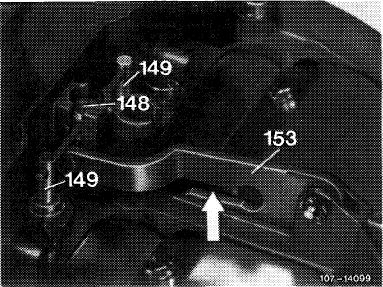
2 Remove transmitting lever (153) and guide pin (148).
|
|||
|
148 Guide pin
149 Jet needle
153 Transmitting lever
|
|||
|
|
|||
|
07.2.2 la—172/1
|
|||
|
|
|||
|
|
|||
|
3 Place carburetor cover on two supports in such a manner that the jet needles (149) are unobstructed at bottom end. Let jet needles (149) be seated in main jets (159).
|
 |
||
|
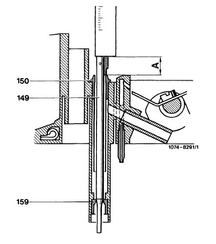
Measuring dimension „A’
|
|||
|
|
|||
|
4 Measure dimension „A” with depth gauge from face of jet needles to upper flange of air correction nozzles (150) and write down.
Note: Dimension „A” should be approximately the same on both sides. Deviations in excess of 0.5 mm indicate that the main jet has been subject to creep. In such a case, renew carburetor cover.
|
 |
||
|
Measuring dimension „A’
|
|||
|
|
|||
|
07.2.2 la-172/2
|
|||
|
|
|||
|
|
|||
|
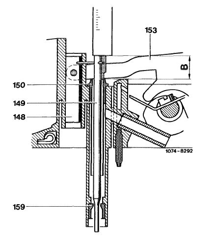
5 Reinstall guide pin (148) and transmitting lever (153) and measure dimension „B” from face of jet needles to upper flange of air correction jets (150) and correct, if required.
Dimension „B” should be similar to dimension „A” + 0.3 mm.
|
 |
||
|
Measuring example:
Measured dimension „A” = 7.7 mm
+ 3.3 mm
|
|||
|
Dimension „B” should be 11.0 mm
|
|||
|
Measuring dimension „B”
|
|||
|
|
|||
|
Slight and one-sided deviations of dimension „B” should be corrected by pertinent bending of guide pin (148) arms.
Decreasing dimension „B” = leaner Increasing dimension „B” = richer
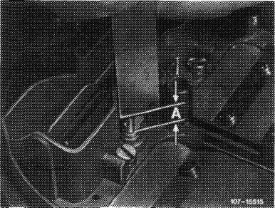
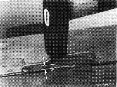
If dimension „B” is the same on both sides but essentially too high, correct as follows:
Remove transmitting lever (153) (do not remove jet needles). Clamp removed transmitting lever into vise in such a manner that only the actuating arm of the jet needles projects. Reduce gap (arrows) by max. 0.3 mm by means of a light hammer blow and repeat test.
|
 |
||
|
|
|||
|
Attention!
When installing transmitting lever, make sure that the fastening pin can be slipped in free of tension so that air valve will not bind, since this will result in bypass faults.
|
|||
|
|
|||
|
07.2.2 la-172/3
|
|||
|
|
|||