Adjustment of idle speed
|
|
|||||||||||||||||||||||||||||||||||||||||||||||||||||||||||||
|
07.3—100 Adjustment of idle speed
|
|||||||||||||||||||||||||||||||||||||||||||||||||||||||||||||
|
|
|||||||||||||||||||||||||||||||||||||||||||||||||||||||||||||
|
A. Standard version
|
|||||||||||||||||||||||||||||||||||||||||||||||||||||||||||||
|
|
|||||||||||||||||||||||||||||||||||||||||||||||||||||||||||||
|
Checking and adjusting data
|
|||||||||||||||||||||||||||||||||||||||||||||||||||||||||||||
|
|
|||||||||||||||||||||||||||||||||||||||||||||||||||||||||||||
|
Engine
|
Idle speed 1/min
|
Idle speed emission value %CO
|
|||||||||||||||||||||||||||||||||||||||||||||||||||||||||||
|
|
|||||||||||||||||||||||||||||||||||||||||||||||||||||||||||||
|
110.984/985 110.986/987
|
750-850
|
||||||||||||||||||||||||||||||||||||||||||||||||||||||||||||
|
|
|||||||||||||||||||||||||||||||||||||||||||||||||||||||||||||
|
0.5-1.5
|
|||||||||||||||||||||||||||||||||||||||||||||||||||||||||||||
|
|
|||||||||||||||||||||||||||||||||||||||||||||||||||||||||||||
|
110.988 110.989 110.990
|
700-800
|
||||||||||||||||||||||||||||||||||||||||||||||||||||||||||||
|
|
|||||||||||||||||||||||||||||||||||||||||||||||||||||||||||||
|
Special tools
|
|||||||||||||||||||||||||||||||||||||||||||||||||||||||||||||
|
|
|||||||||||||||||||||||||||||||||||||||||||||||||||||||||||||
|
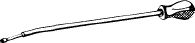
Screw driver 3 mm with tommy handle for regulating idle speed emission value
|
 |
000 589 14 11 00
|
|||||||||||||||||||||||||||||||||||||||||||||||||||||||||||
|
|
|||||||||||||||||||||||||||||||||||||||||||||||||||||||||||||
|
Puller
|
123 589 05 33 00
|
||||||||||||||||||||||||||||||||||||||||||||||||||||||||||||
|
|
|||||||||||||||||||||||||||||||||||||||||||||||||||||||||||||
|
11004-8204
|
|||||||||||||||||||||||||||||||||||||||||||||||||||||||||||||
|
|
|||||||||||||||||||||||||||||||||||||||||||||||||||||||||||||
|
Installer
|
 |
123 589 00 15 00
|
|||||||||||||||||||||||||||||||||||||||||||||||||||||||||||
|
|
|||||||||||||||||||||||||||||||||||||||||||||||||||||||||||||
|
Oil telethermometer
|
 |
116 589 27 21 00
|
|||||||||||||||||||||||||||||||||||||||||||||||||||||||||||
|
|
|||||||||||||||||||||||||||||||||||||||||||||||||||||||||||||
|
|||||||||||||||||||||||||||||||||||||||||||||||||||||||||||||
|
|
|||||||||||||||||||||||||||||||||||||||||||||||||||||||||||||
|
Note
|
|||||||||||||||||||||||||||||||||||||||||||||||||||||||||||||
|
|
|||||||||||||||||||||||||||||||||||||||||||||||||||||||||||||
|
On light alloy fuel distributor, removal of air cleaner for adjusting emission value at idle is no longer necessary.
Do not adjust idle speed when engine is too hot, e.g. immediately after a fast drive or after measuring output on chassis dynamometer.
|
|||||||||||||||||||||||||||||||||||||||||||||||||||||||||||||
|
|
|||||||||||||||||||||||||||||||||||||||||||||||||||||||||||||
|
07.3.2 lla-100/1 F2
|
|||||||||||||||||||||||||||||||||||||||||||||||||||||||||||||
|
|
|||||||||||||||||||||||||||||||||||||||||||||||||||||||||||||
|
|
|||
|
Adjusting
|
|||
|
|
|||
|
1 Switch off air-conditioning system or automatic climate control. Move selector lever into position
|
|||
|
|
|||
|
2 Remove air cleaner, with gray iron fuel distributor only.
3 Connect test instruments: Revolution counter, CO-measuring instrument, digital tester, oil telethermo-meter.
|
|||
|
|
|||
|
4 Run engine to 75—85 °C oil temperature.
5 Check intake system for leaks. For this purpose, spray all sealing points with Iso-Oktan DIN 51 756 or benzine.
Attention!
Do not use conventional fuel for spraying (unhealthy vapors). Pay attention to inflammability and do not spray on red-hot parts or components of ignition system.
|
|||
|
|
|||
|
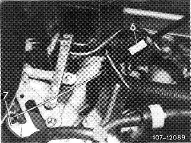
6 Vehicles with cruise control/tempomat:
|
 |
||
|
Cruise control/tempomat, pneumatic
Check whether bowden wire for cruise control/tempomat rests free of tension against regulating lever (7).
Set with adjusting nut (6), if necessary.
|
|||
|
|
|||
|
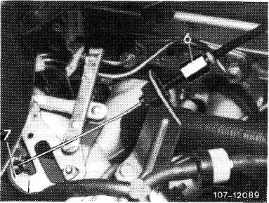
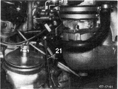
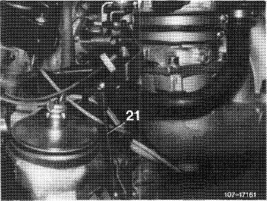
Cruise control/tempomat, electrical
Check whether actuator rests against idle speed stop of cruise control/tempomat. For this purpose, disconnect pull rod (21) and push lever of actuator clockwise to idle speed stop.
When connecting pull rod (21), make sure that the lever of the actuator is raised by approx. 1 mm from idle speed stop. Adjust pull rod, if required.
|
 |
||
|
|
|||
|
07.3.2 Ha—100/2 F2
|
|||
|
|
|||
|
|
|||
|
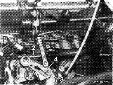
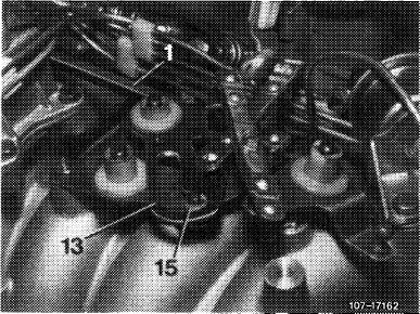
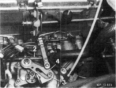
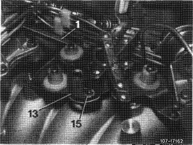
7 Check whether roller (3 and 15) in slotted lever (4 and 13) rests free of play against end stop. Adjust with connecting rod (1 and 2), if required.
|
 |
||
|
Model 123
|
|||
|
|
|||
|
Model 126
|
 |
||
|
|
|||
|
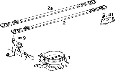
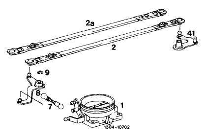
Connecting rod can be adjusted on one side only. Pay attention to installation position (refer to Fig.)
|
|||
|
|
|||
|
2 Former version 2a Present version
|
 |
||
|
1304-10702
|
|||
|
|
|||
|
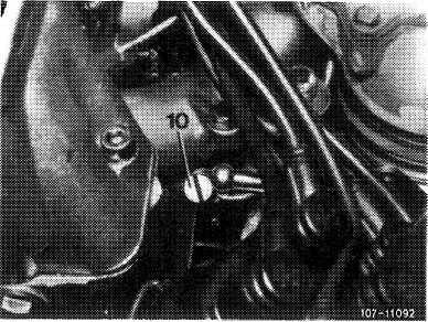
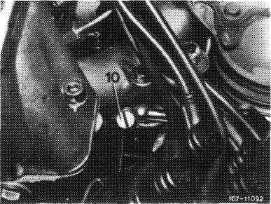
8 Set to specified speed by means of idle speed adjusting screw (10).
|
 |
||
|
|
|||
|
07.3.2 Ha—100/3 F2
|
|||
|
|
|||
|
|
|||
|
9 Adjusting idle speed emission value:
|
 |
||
|
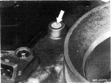
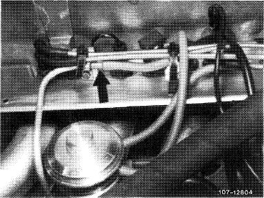
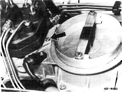
With gray iron fuel distributor
Unscrew closing plug (arrow).
Attention!
On vehicles manufactured after 1.10.1976, remove safety plug first.
|
|||
|
|
|||
|
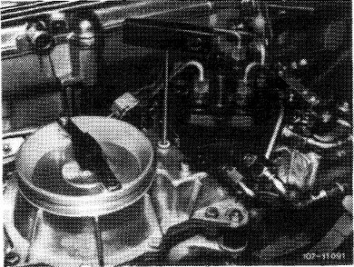
Insert screw driver through bore on idle speed mixture control screw and set emission value by turning screw.
Turning counterclockwise = leaner Turning clockwise = richer
Close bore for closing plug. Accelerate for a short moment, check idle speed emission value and readjust, if required.
|
 |
||
|
|
|||
|
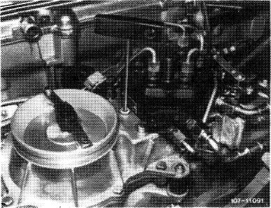
Following adjustments on vehicles manufactured after 1.10.1976, engines were provided with a blue safety plug (arrow), MB part no. 000 997 59 86.
|
 |
||
|
|
|||
|
07.3.2 lla-100/4 F2
|
|||
|
|
|||
|
|
|||
|
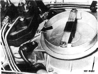
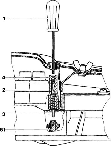
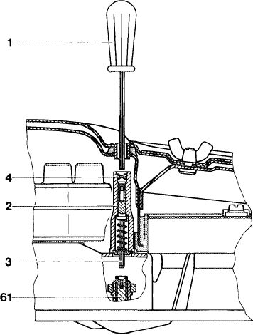
With light alloy fuel distributor
Pull out safety plug (4) by means of puller.
Push with screw driver (1) through recess on air cleaner top against adjusting device (2). Push adjusting device down with screw driver against spring force, turn slightly until hexagon (3) engages in mixture control screw (61).
|
1073-8838
|
||
|
Turning counterclockwise = leaner Turning clockwise = richer
Release screw driver, the compression spring will then force adjusting device out of mixture control screw.
|
|||
|
1 Screw driver
2 Adjusting device
3 Hexagon
4 Safety plug
61 Mixture control screw
|
|||
|
|
|||
|
Accelerate for a short moment, check idle speed emission value and readjust, if required.
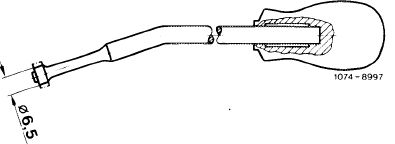
Following adjustment, install a blue fuse plug (4), part no. 000 997 56 86 by means of installer.
|
|||
|
|
|||
|
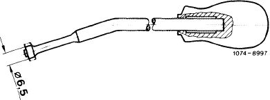
Note: The diameter of the installer for knocking-in safety plug for protective cap of mixture control screw (61) has been changed from 8 mm to 6.5 mm.
In spare parts sector, only installers with changed diameter are now available. On former installers, grind diameter down to 6.5 mm.
|
 |
||
|
|
|||
|
10 With gray iron fuel distributor, mount air cleaner. Check idle speed emission value once again and readjust, if required.
11 Place selector lever into driving position, switch-on air conditioning, turn power steering to full lock, with engine running. Readjust engine speed, if required.
|
|||
|
|
|||
|
07.3.2 lla-100/5 F2
|
|||
|
|
|||
|
|
||||||
|
Identification label: Identification label in national language on radiator cross member. Adjust engines according to data of respective emission label.
|
||||||
|
|
||||||
|
Testing and adjusting values
|
||||||
|
|
||||||
|
National version
and
model year
|
Idle speed 1/min
|
Idle speed emission value % CO without air injection
|
||||
|
|
||||||
|
(AUS)
Label: color code silver.
|
||||||
|
|
||||||
|
1977-1980
|
800
|
0.5-1.5
|
||||
|
|
||||||
|
1981/82
|
750-850
|
0.3-1.3
|
||||
|
|
||||||
|
Label: in Japanese language.
|
||||||
|
|
||||||
|
1977-1980
|
800
|
0.4-2.0
|
||||
|
|
||||||
|
Label: color code blue.
|
||||||
|
|
||||||
|
1977-1980
|
800
|
0.5-1.5
|
||||
|
|
||||||
|
1981/82
|
750-850
|
0.3-1.3
|
||||
|
|
||||||
|
Label: color code Federal black, California yellow.
|
||||||
|
|
||||||
|
1977-1979
|
800
|
0.4-2.0
|
||||
|
|
||||||
|
Special tools
|
||||||
|
|
||||||
|
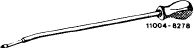
Screw driver 3 mm with tommy handle for readjusting idle speed emission value
|
 |
110O4-7807
|
000 589 14 11 00
|
|||
|
|
||||||
|
Puller
|
123 589 05 33 00
|
|||||
|
|
||||||
|
11004-8204
|
||||||
|
|
||||||
|
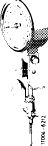
Installer
|
11004-8278
|
123 589 00 15 00
|
||||
|
|
||||||
|
Oil telethermometer
|
 |
116 589 27 21 00
|
||||
|
|
||||||
|
07.3.2 I la-100/6 F2
|
||||||
|
|
||||||
|
|
|||
|
Conventional testing instruments and accessories
|
|||
|
|
|||
|
CO-measuring instrument, revolution counter
|
|||
|
|
|||
|
Digital tester
|
e.g. made by Bosch, MOT 001.03
|
||
|
|
|||
|
Note
|
|||
|
|
|||
|
For adjustment of emission value at idle with light alloy fuel distributor, removal of air cleaner is no longer required.
Do not adjust idle speed if engine is too hot, e.g. immediately after a fast drive or after measuring output on chassis dynamometer.
|
|||
|
|
|||
|
Adjustment
|
|||
|
|
|||
|
1 Switch off air conditioning or automatic climate control. Move selector lever into position „P”.
2 With gray iron fuel distributor, remove air cleaner.
3 Connect test instruments.
• Revolution counter
• CO-measuring instrument
• Digital tester
• Oil telethermometer
|
|||
|
|
|||
|
Connecting CO-measuring instrument
For this purpose, on (^T)and(usA)version, pull conect-ing hose (arrow) from measuring point (exhaust backpressure line).
Respective model years: ©1977-1980 (usa) 1977-1979
Connect CO-measuring instruments and exhaust backpressure line with a hose.
No catalyst is installed on <@)tourist vehicles, for this reason, the emission value can be measured at exhaust tail pipe.
|
 |
||
|
|
|||
|
07.3.2 lla-100/7 F2
|
|||
|
|
|||
|
|
|||
|
4 Run engine to 75—85 °C oil temperature.
5 Check intake system for leaks. For this purpose, spray all sealing points with Iso-Oktan DIN 51756 or benzine.
Attention!
Do not use conventional fuel for spraying (unhealthy vapors). Pay attention to inflammability and do not spray on red-hot parts or components of ignition system.
|
|||
|
|
|||
|
6 Vehicles with cruise control/tempomat:
|
 |
||
|
Cruise control/tempomat, pneumatic
Check whether Bowden for cruise control/tempomat rests free of tension against regulating lever (7). Set with adjusting screw (6) if required.
|
|||
|
|
|||
|
Cruise control/tempomat, electrical
Check whether actuator rests against idle speed stop of cruise control/tempomat. For this purpose, disconnect pull rod (21) and push lever of actuator clockwise to idle speed stop.
When connecting pull rod (21), make sure that the lever of the actuator is raised from idle speed stop by approx. 1 mm. Adjust pull rod, if required.
|
 |
||
|
|
|||
|
7 Check whether roller (3 and 15) in slotted lever (4 and 13) rests free of tension against final stop. Adjust with connecting rod (1 and 2), if required.
|
 |
||
|
Model 123
|
|||
|
|
|||
|
07.3.2 lla-100/8 F2
|
|||
|
|
|||
|
|
|||
|
Model 126
|
 |
||
|
|
|||
|
Connecting rod can be adjusted on one side only. Pay attention to installation position (refer to Fig.).
|
 |
||
|
2 Former version 2a Present version
|
|||
|
|
|||
|
8 Set to specified engine speed by means of idle speed air screw (10).
|
 |
||
|
|
|||
|
9 Check idle speed emission value.
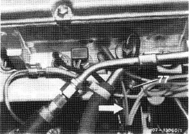
(aus) 1977-1982 ©1977-1982
Check idle speed emission value without air injection. For this purpose, pull blue/purple vacuum line (arrow) from delay valve (77) and close small tube. This will disconnect air injection.
|
 |
||
|
|
|||
|
07.3.2 Ma—100/9 F2
|
|||
|
|
|||
|
|
|||
 |
|||
|
|
|||
|
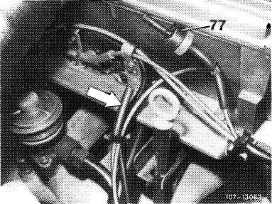
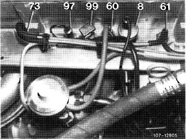
©1977-1980 ©1977-1979
Check idle speed emission value without air injection, in cylinder head. For this purpose, pull blue vacuum line from blue thermo valve (60) and close line. This will disconnect air injection.
|
 |
||
|
|
|||
|
10 Adjust idle speed emission value:
|
 |
||
|
With gray iron fuel distributor
|
|||
|
For this purpose, unscrew closing plug (arrow).
|
|||
|
Insert screw driver through bore against idle speed mixture control screw and adjust emission value by turning screw.
Turning counterclockwise = leaner Turning clockwise = richer
Close bore for closing plug. Accelerate for a short moment, check idle speed emission value once again and readjust, if required.
Put back vacuum line on thermo valve.
Check idle speed emission value again (air injection operational). The idle speed emission value should be below previously set value.
|
|||
 |
|||
|
|
|||
|
07.3.2 lla-100/10 F2
|
|||
|
|
|||
|
|
||||
|
With light alloy fuel distributor
Pull out safety plug (4) with puller.
Insert screw driver (1) through cutout on air cleaner top and push against adjusting device (2). Push adjusting device down with screw driver against force of spring, turn slightly until hexagon (3) engages in mixture control screw (61).
|
 |
1073-8838
|
||
|
Turning counterclockwise = leaner Turning clockwise = richer
Release screw driver, the compression spring will disengage adjusting device from mixture control screw.
|
||||
|
1 Screw driver
2 Adjusting device
3 Hexagon
4 Safety plug
61 Mixture control screw
|
||||
|
|
||||
|
Accelerate for a short moment, check idle speed emission value and readjust, if required.
Following adjustment, install a blue safety plug (4), part no. 000 997 56 86 by means of installer.
|
||||
|
|
||||
|
Note: The diameter of the installer for knocking-in safety plug for protective cap of mixture control screw (61) has been changed from 8 mm to 6.5 mm.
In spare parts sector, only the installers with changed diameter are now available. On former installers, grind diameter down to 6.5 mm.
|
 |
|||
|
|
||||
|
11 With gray iron fuel distributor, mount air cleaner. Check idle speed and idle speed emission value once again and adjust, if required.
12 Place selector lever into driving position, engage air conditioning, turn power steering to full lock, while keeping engine running. Readjust engine speed, if required.
|
||||
|
|
||||
|
07.3.2 lla-100/11 F2
|
||||
|
|
||||