Adjustment of regulating linkage
|
|
|||||||||||||||||||||||||||||||||||
|
07.2—300 Adjustment of regulating linkage
|
|||||||||||||||||||||||||||||||||||
|
|
|||||||||||||||||||||||||||||||||||
|
Length of regulating rods in mm1)
|
|||||||||||||||||||||||||||||||||||
|
|
|||||||||||||||||||||||||||||||||||
|
|||||||||||||||||||||||||||||||||||
|
|
|||||||||||||||||||||||||||||||||||
|
l) Measured from center of ball socket to center of ball socket.
|
|||||||||||||||||||||||||||||||||||
|
|
|||||||||||||||||||||||||||||||||||
|
Testing, adjusting
|
 |
||||||||||||||||||||||||||||||||||
|
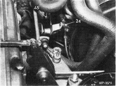
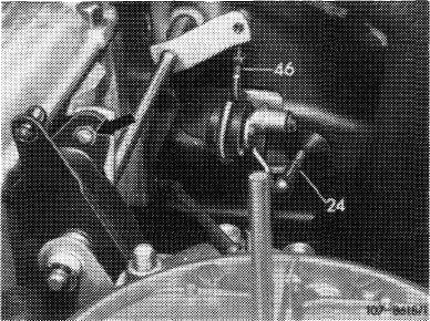
1 Disconnect regulating rods (24 and 46), check for specified length, adjust if required and reconnect.
|
|||||||||||||||||||||||||||||||||||
|
Model 114
|
|||||||||||||||||||||||||||||||||||
|
|
|||||||||||||||||||||||||||||||||||
|
Model 116
|
 |
||||||||||||||||||||||||||||||||||
|
|
|||||||||||||||||||||||||||||||||||
|
07.2.2 lb-300/1
|
|||||||||||||||||||||||||||||||||||
|
|
|||||||||||||||||||||||||||||||||||
|
|
|||
|
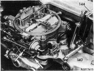
2 Adjust regulating rod (130). For this purpose, disconnect regulating rod, check for specified length, adjust if required and reconnect.
3 Adjust regulating rod (144). For this purpose, disconnect regulating rod, check for specified length, adjust if required and reconnect.
|
 |
||
|
|
|||
|
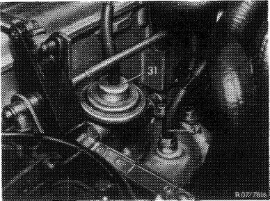
Layout regulation
@) 1973/74 Federal (USA) 1974 California
|
 |
||
|
|
|||
|
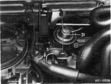
Layout regulation
CD 1976 (USA) 1975/76
|
 |
||
|
|
|||
|
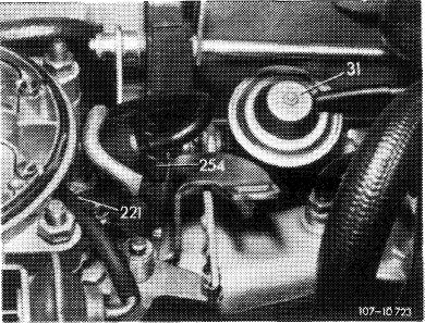
Layout regulation (T) 1976
|
 |
||
|
|
|||
|
07.2.2 lb-300/2
|
|||
|
|
|||
|
|
|||
|
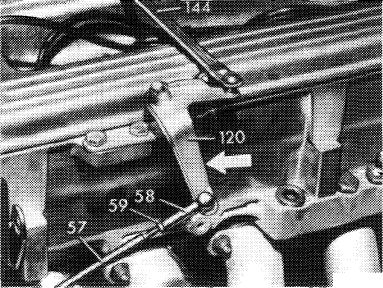
4 Adjust control pressure rod (57) for automatic transmission. Keep engine running. Disconnect control pressure rod and push toward the rear up to stop. Push angle lever (120) in direction of arrow until idle travel in regulating rod (140 in fig. item 3) is cancelled.
Then adjust ball socket (58) until socket can be connected again free of tension.
|
a 27/73$*
|
||
|
|
|||
|
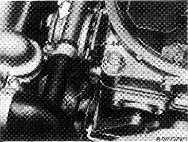
5 Adjust full throttle stop. Check and adjust only with stage II unlocked. For this purpose, push fast idle cam (44) completely down (not required if engine is at operating temperature).
|
 |
||
|
|
|||
|
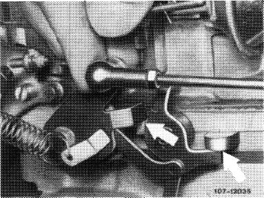
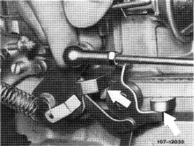
With the engine stopped, depress accelerator pedal only up to stop on kickdown switch (do not actuate kickdown switch). The throttle valve lever of I. and II. stage should rest against full throttle stop (arrows).
|
 |
||
|
|
|||
|
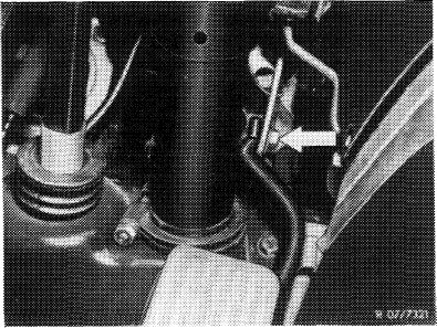
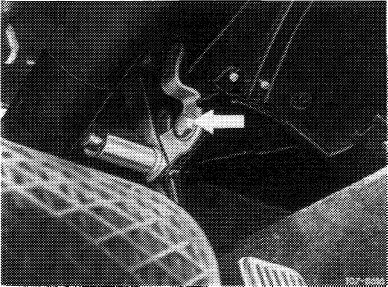
If the full throttle stop is not attained on model 114 or 116, loosen clamping screw (arrow) on regulating shaft. Slightly pull up accelerator pedal and tighten screw again. Check full throttle stop once again.
|
 |
||
|
Model 114
|
|||
|
|
|||
|
07.2.2 lb-300/3
|
|||
|
|
|||
|
|
|||
|
Model 116
|
 |
||
|
|
|||
|
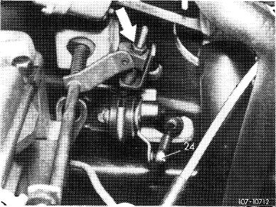
On model 116 with stepless full throttle stop adjustment, set adjusting nut (arrow) accordingly.
|
 |
||
|
|
|||
|
Adjustment on vehicles with righthand steering
|
 |
||
|
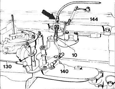
The adjusting lengths are similar to lefthand steering vehicles, the same applies to adjustment. Following adjustment with engine stopped, step down fully on accelerator pedal (with automatic transmission, apply kickdown). The throttle valve lever of stage I and II should rest free of tension against full throttle stop of carburetor (arrows).
|
|||
|
|
|||
|
If the full throttle stop on carburetor is not attained, readjust Bowden wire (arrow).
|
 |
||
|
|
|||
|
1074-8320
|
|||
|
|
|||
|
07.2.2 lb-300/4
|
|||
|
|
|||
