Removal and installation of fuel pump
|
|
|||||
|
07.2—212 Removal and installation of fuel pump
|
|||||
|
|
|||||
|
Special tool
|
|||||
|
|
|||||
|
Clamp
|
 |
000 589 40 37 00
|
|||
|
|
|||||
|
Note
|
SW13 DIN 837
|
||||
 |
|||||
|
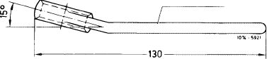
To facilitate loosening or tightening of fastening screws during removal and installation of fuel pump, particularly on vehicles with power steering, offset a conventional box wrench as shown in illustration.
|
|||||
|
|
|||||
|
Removal
|
 |
||||
|
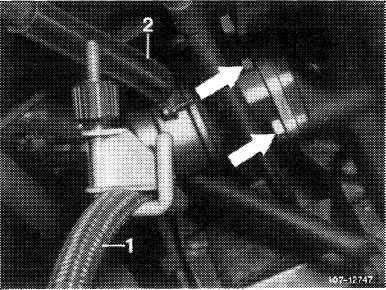
1 Pinch suction hose. Pull off suction and pressure hose.
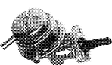
2 Unscrew fastening screws (arrows), remove fuel pump and sealing flange.
|
|||||
|
(usa) 1973/74
1 Suction hose
2 Pressure hose
|
|||||
|
|
|||||
|
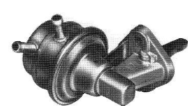
For (2)1976, (T)1976, (@»1974 California an angular fuel pump is installed for lack of space due to air pump.
|
 |
||||
|
|
|||||
|
07.2.2 Ib—212/1
|
|||||
|
|
|||||
|
|
||||
|
Angular fuel pump with removable cover
<@) 1974 California (@) 1975/76 CT) 1976
|
 |
|||
|
707-9099
|
||||
|
|
||||
|
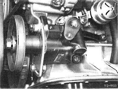
Angular fuel pump without removable cover with fuel shutoff valve (roll-over test)
|
 |
|||
|
Code number:
|
PE 20 215 (arrow)
©1976 (usa) 1976
|
|||
|
107-10953
|
||||
|
|
||||
|
Installation
|
 |
|||
|
3 For installation proceed vice versa.
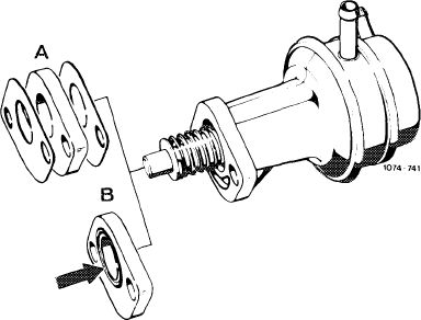
Note: For better sealing, starting May 1976, a sealing flange (B) with two O-rings (arrow) is installed between the fuel pump or angle piece and crankcase.
|
||||
|
|
||||
|
Repair instructions
|
 |
|||
|
a) Fuel pumps attached directly to crankcase by means of a sealing flange
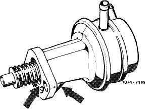
For this type of arrangement, the sealing flange with two O-rings may be installed throughout only with a fuel pump provided with stiffening ribs (arrows).
|
||||
|
|
||||
|
07.2.2 tb—212/2
|
||||
|
|
||||
|
|
||
|
b) Fuel pumps attached to an angle piece (engines with air pump)
With this arrangement, the sealing flange can be installed with two O-rings between angle piece and crankcase.
The respectively installed or available fuel pump (with or without stiffening ribs) may be used.
Attention!
When installing sealing flange, make sure in both cases that the O-ring rests on crankcase with its entire circumference, i.e. serves as a seal.
For this purpose, clean sealing surface on crankcase and apply a coat of chalk, talcum or india ink to O-ring. Press sealing flange with O-ring against crankcase. Use the two fastening screws for centering. Then evaluate contact surface. If the O-ring is not resting on its entire circumference, remove O-ring at crankcase end from sealing flange and install a paper gasket.
Note: Provide screws for attachment to crankcase prior to assembly with sealing compound (e.g. Hylomar) on threads.
|
||
|
|
||
|
07.2.2 lb-212/3
|
||
|
|
||