Technical modifications (revisions) of model years
|
|
|||
|
07.2—092 Technical modifications (revisions) of model years
|
|||
|
|
|||
|
Notes
|
|||
|
|
|||
|
Below is a description of the different carburetor systems in relation to standard version or model years in relation to each other. Further below are the modifications introduced during the model year.
|
|||
|
|
|||
|
A. © model year 1976
Differences as compared with standard version
• Float chamber vent valve
• Full load enrichment in stage I no longer applicable
• Idle speed combination jet
• Vacuum connection for vacuum booster of EGR
• Carburetor cover with raised centering flange for air filter
• Draw-off connection for fuel evaporation control system and crankcase breather
• Pre-atomizer with slot
• New nozzle line-up (refer to adjusting data)
• New insulating flange
• Choke cover-stepped heater
|
|||
|
|
|||
|
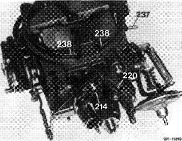
214 Float chamber vent valve (vacuum-actuated)
237 Vacuum connection for vacuum booster of EGR
238 Idle speed combination jet
|
 |
||
|
|
|||
|
07.2.2 la-092/1
|
|||
|
|
|||
|
|
|||
|
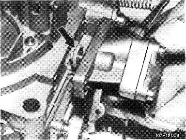
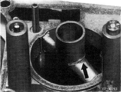
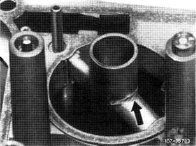
Float chamber vent valve
|
 |
||
|
This valve (arrow) is vacuum-controlled. With the engine stopped and the ignition switched off the vent valve is set to external venting, as a result of which the fuel evaporation vapors will flow from float chamber into charcoal canister. This will improve hot starting.
|
|||
|
|
|||
|
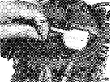
Idle speed combination jet
|
 |
||
|
The idle speed fuel jet and the idle speed air jet are united into a combination jet (238).
Access to idle speed fuel jet is thereby improved. Sealing is by means of a sealing ring (239).
|
|||
|
|
|||
|
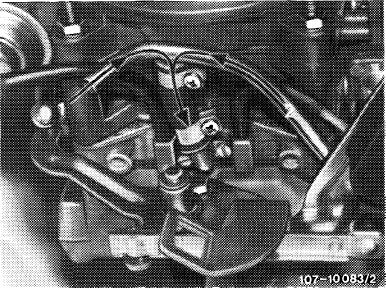
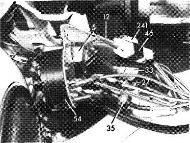
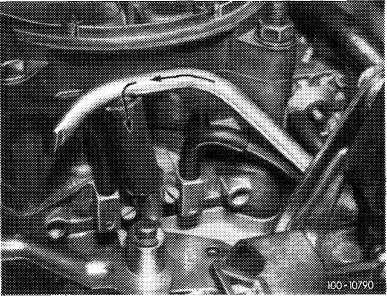
Draw-off connection for fuel evaporation control system and crankcase breather
|
 |
||
|
The fuel evaporation vapors from float chamber and fuel tank stored in charcoal canister, as well as the vapors of the crankcase venting system are drawn off in direction of arrow by way of a draw-off connection at the rear on carburetor while the engine is running.
|
|||
|
1 From charcoal canister
2 From crankcase venting system
|
|||
|
|
|||
|
Pre-atomizer with slot
|
 |
||
|
The pre-atomizer is provided with a slot (arrow) to improve atomization of the fuel.
|
|||
|
|
|||
|
07.2.2 la-092/2
|
|||
|
|
|||
|
|
|||
|
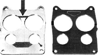
New insulating flange
|
|||
|
|
|||
|
The new insulating flange is provided with a groove (arrow) by means of which the fuel evaporation vapors and the crankcase evaporation vapors are drawn off into stage II.
|
 |
||
|
|
|||
|
107-9 854/1
|
|||
|
|
|||
|
Choke cover-stepped heater
|
107-10044
|
||
|
To improve the warming-up characteristics the starter cover of the automatic choke is heated in two steps. Below 17 °C oil temperature at reduced output via pre-resistor (46), above 17 °C oil temperature the choke cover is heated at normal output.
|
|||
|
46 Pre-resistor for choke cover-stepped heater
|
|||
|
|
|||
|
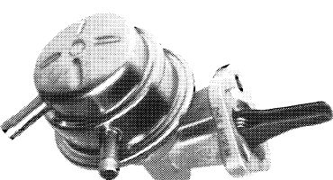
Fuel pump
|
|||
|
|
|||
|
Following the installation of the air pump for air injection, the available space made the installation of a fuel pump with angle drive necessary.
The closing cap is brazed to housing and can no longer be removed. Cleaning of the filter strainer is no longer necessary.
|
 |
||
|
|
|||
|
107-10953/1
|
|||
|
|
|||
|
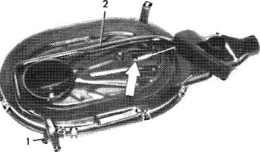
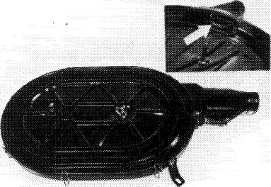
Air filter
|
|||
|
|
|||
|
The expanding element (arrow) for controlling the intake air preheater has been moved inside air filter.
For air injection the air filter is provided with an additional hose connection (1). For reasons of available space, the air injection line (2) is attached below to air filter.
|
 |
||
|
|
|||
|
109-10802/2
|
|||
|
|
|||
|
07.2.2 la-092/3
|
|||
|
|
|||
|
|
|||
|
B. © model year 1976
Differences as compared with standard version
|
|||
|
|
|||
|
• Idle speed combination nozzle
• Needle-controlled enrichment in stage I no longer applicable
• Vacuum connection (237) on carburetor cover for vacuum booster of EGR
• Carburetor cover with raised centering flange for air filter
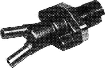
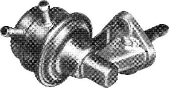
• New fuel return valve with fuel pressure control
• New expanding element for thermostatically controlled bypass choke (TN choke)
• Thermo delay valve for choke
• Choke cover-stepped heater
• Pre-atomizer with slot
• Draw-off connection for crankcase ventilation
• Orifice (throttle) in hose to vacuum governor
• Jet line-up (refer to adjusting data)
|
|||
|
|
|||
|
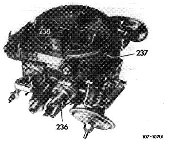
236 Thermostatically controlled bypass choke (TN choke)
237 Vacuum connection for vacuum booster of EGR
238 Idle speed combination jet
|
 |
||
|
|
|||
|
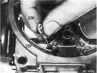
Idle speed combination jet
|
 |
||
|
The idle speed fuel and idle speed air jets are united into a combination jet (238) which can be removed in upward direction.
Access to idle speed fuel jet is thereby improved. Sealing by means of rubber sealing ring (239).
|
|||
|
|
|||
|
07.2.2 la-092/4
|
|||
|
|
|||
|
|
|||
|
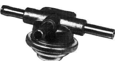
New fuel return valve with fuel pressure regulation
|
|||
|
|
|||
|
The new fuel return valve is simultaneously designed as a fuel pressure regulator. Regulation of the fuel return flow rate and the fuel pressure to approx. 0.2 bar gauge pressure is performed by means of a spring-loaded valve. Fuel level fluctuations will then be widely avoided.
The former vacuum connection on fuel return valve is no longer applicable.
The new fuel return valve can also be installed on carburetors used up to now. Vacuum hose for fuel return valve and distributor are no longer installed. Vacuum hose from vacuum governor is directly plugged on connection „C” on throttle valve member.
|
 |
||
|
W7-107O5
|
|||
|
|
|||
|
New expanding element for thermostatically controlled bypass choke (TN choke)
|
 |
||
|
The dimensions of the new expanding element are larger and the housing had to be enlarged accordingly.
The new TN choke can also be installed on the type of carburetors used up to now.
|
|||
|
|
|||
|
K)7-10704
|
|||
|
|
|||
|
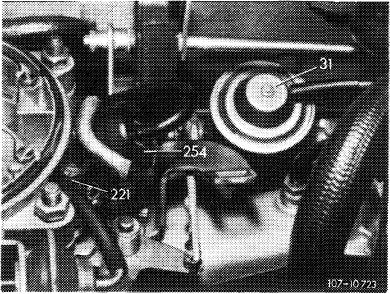
Thermo delay valve for choke
|
 |
||
|
The thermo delay valve makes sure that at temperatures above approx. —12 °C the choke valve is not immediately pulled after the engine is started, but at a delay. There is no delay by the thermo delay valve at temperatures below approx. —12 °C.
|
|||
|
254 Thermo delay valve
|
|||
|
|
|||
|
07.2.2 la-092/5
|
|||
|
|
|||
|
|
|||
|
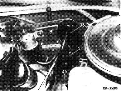
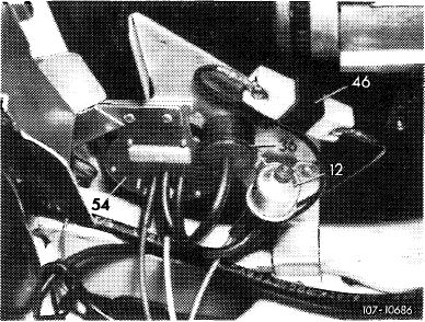
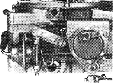
Choke cover-stepped heater
|
 |
||
|
The choke cover of the automatic carburetor choke is heated in two steps. Below 17 °C oil temperature at reduced output by way of a pre-resistor (46), above 17 °C oil temperature the choke cover is heated directly.
|
|||
|
Model 114
46 Pre-resistor for choke cover-stepped heater
|
|||
|
|
|||
|
Model 116
46 Pre-resistor for choke cover-stepped heater
|
 |
||
|
|
|||
|
Pre-atomizer with slot
|
 |
||
|
The pre-atomizer has a slot (arrow), by means of which the atomization of the fuel is still further improved.
|
|||
|
|
|||
|
Draw-off connection for crankcase ventilation
The crankcase evaporation vapors are guided from cylinder head to draw-off connection at the rear on carburetor and are drawn off by the engine below throttle valves of stage II in direction of arrow.
Throttle in hose to vacuum governor
A throttle is installed in line to vacuum governor. As a result, the throttle valve will be dampened when returning to idle upon deceleration.
|
 |
||
|
|
|||
|
07.2.2 la-092/6
|
|||
|
|
|||
|
|
|||
|
Insulating flange
|
|||
|
|
|||
|
To guide the starting and warming-up mixture from thermostatically controlled bypass choke into intake pipe, the insulating flange has been given a wide groove between stages I, and a narrow groove between stages II for drawing off crankcase evaporation vapors.
Attention!
Do not install this insulating flange in carburetors used up to now.
|
 |
||
|
|
|||
|
107-9854
|
|||
|
|
|||
|
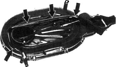
Air cleaner
|
|||
|
|
|||
|
The air cleaner is provided with an additional hose connection for air relief (air discharge).
For reasons of available space, the air relief (air discharge) is attached below on cleaner.
|
 |
||
|
|
|||
|
109-10802
|
|||
|
|
|||
|
Fuel pump
|
|||
|
|
|||
|
For lack of space following installation of air pump for air relief (air discharge) the fuel pump had to be provided with an angle drive.
|
 |
||
|
|
|||
|
107-9099
|
|||
|
|
|||
|
07.2.2 la-092/7
|
|||
|
|
|||
|
|
|||
|
C. <®> model year 1973 Federal
Differences as compared with standard version
|
|||
|
|
|||
|
• Needle-controlled enrichment in stage I no longer applicable
• Float chamber vent shaft with protective flange cover
• Modified jet line-up, new jet needle for stage II
• Location of vacuum bores changed
• New insulating flange
|
|||
|
|
|||
 |
|||
|
|
|||
|
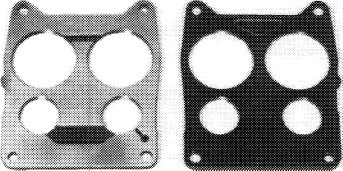
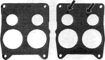
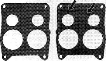
Insulating flange
|
|||
|
|
|||
|
The insulating flange is provided with two grooves (arrows) along which a portion of the emissions is returned to intake pipe.
|
 |
||
|
|
|||
|
Left = top Right = bottom
|
|||
|
|
|||
|
Air filter
|
|||
|
An additional flap (arrow) is mounted in air filter intake pipe above connection for intake air preheater. The flap prevents the escape of fuel evaporation vapors of warm engine as a result of preheating the intake air.
|
 |
||
|
|
|||
|
07.2.2 la-092/8
|
|||
|
|
|||
|
|
||
|
Modifications in model year 1973
|
||
|
|
||
|
Insulating flange
The grooves (arrows) for controlling the exhaust gas return volume were milled flatter to reduce the respective exhaust emission volume.
This in turn improved driving characteristics at partial load (complaints about bucking). Former insulating flanges can be exchanged for modified version.
|
||
|
|
||
 |
||
|
|
||
|
Left = top Right = bottom
|
||
|
|
||
|
Identification
Depth of grooves (arrows) 2.3 mm (formerly 3.0 mm).
Start of production: October 1972
Model Starting chassis end no.
114.060 006 650
114.073 001326
|
||
|
|
||
|
07.2.2 la-092/9
|
||
|
|
||
|
|
||||||||||||||||||||||||||||
|
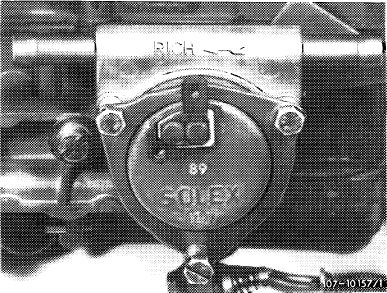
Choke cover
|
 |
|||||||||||||||||||||||||||
|
The choke cover heater has been changed to 12 ohms (16 ohms before).
The bimetallic spring is now heated faster, the automatic choke is shut off earlier. Former choke cover exchangeable for modified version.
|
||||||||||||||||||||||||||||
|
89 Choke cover code number
|
||||||||||||||||||||||||||||
|
|
||||||||||||||||||||||||||||
|
Identification
|
||||||||||||||||||||||||||||
|
|
||||||||||||||||||||||||||||
|
Choke cover code number 89
|
||||||||||||||||||||||||||||
|
|
||||||||||||||||||||||||||||
|
||||||||||||||||||||||||||||
|
|
||||||||||||||||||||||||||||
|
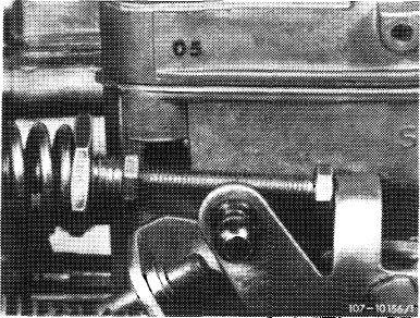
Bypass bores for stage II
|
 |
|||||||||||||||||||||||||||
|
The bypass bores of stage II were set 8 mm deeper and increased to 2 mm dia. (1.3 mm dia. before) (lower arrow).
As a result, improved bypass characteristics from stage I to II. Former carburetor cover exchangeable for modified version.
|
||||||||||||||||||||||||||||
|
Layout bypass bore stage II
Upper arrow = former layout Lower arrow = new layout
|
||||||||||||||||||||||||||||
|
|
||||||||||||||||||||||||||||
|
07.2.2 la-092/10
|
||||||||||||||||||||||||||||
|
|
||||||||||||||||||||||||||||
|
|
|||||||||||||||||||||||||||||
|
Identification
Starting carburetor cover code number 05 modified bypass bores for stage II.
Start of production: January 1973
|
 |
||||||||||||||||||||||||||||
|
Model
|
Starting chassis end no.
|
||||||||||||||||||||||||||||
|
114.060 114.073
|
010 439 002 288
|
||||||||||||||||||||||||||||
|
Carburetor cover code number
|
|||||||||||||||||||||||||||||
|
|
|||||||||||||||||||||||||||||
|
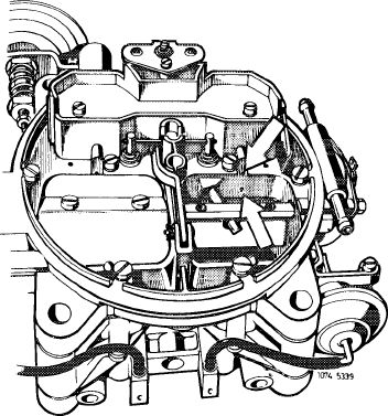
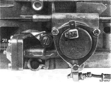
Choke housing
|
 |
||||||||||||||||||||||||||||
|
The choke housing installed up to now with separate sheet metal pulldown has been replaced by a cast iron housing with integrated pulldown and choke valve gap adjusting screw (211).
The choke valve gap adjusting procedure is now easier. Former choke housing exchangeable for modified version.
The carburetor part number has been changed to 000 070 99 04 (000 070 87 04 before).
Choke housing with sheet metal pulldown
|
|||||||||||||||||||||||||||||
|
KV-8941
|
|||||||||||||||||||||||||||||
|
|
|||||||||||||||||||||||||||||
|
Cast iron choke housing with integrated pulldown
|
 |
||||||||||||||||||||||||||||
|
|
|||||||||||||||||||||||||||||
|
Identification
Externally recognized by choke valve gap adjusting screw (211).
|
|||||||||||||||||||||||||||||
|
|
|||||||||||||||||||||||||||||
|
|||||||||||||||||||||||||||||
|
|
|||||||||||||||||||||||||||||
|
07.2.2 la-092/11
|
|||||||||||||||||||||||||||||
|
|
|||||||||||||||||||||||||||||
|
|
||||||
|
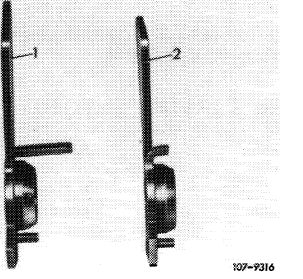
Repair instruction
The modified choke housing can be installed only in combination with a fast idle cam 2nd version (2) with shorter lever.
A longer bolt is used for fastening choke housing. (Subsequent conversion 07.2—140).
|
 |
|||||
|
Fast idle cam versions
1 For choke housing with sheet metal pulldown
2 For cast iron housing with integrated pulldown
|
||||||
|
|
||||||
|
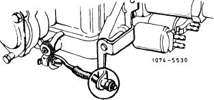
Accelerating pump
|
 |
|||||
|
The adjusting nut with pinch lock has been replaced for a self-locking polystop adjusting nut. Simultaneously the connecting rod has been extended by 2 mm.
As a result, easier adjustment of injection volume.
Subsequent installation is possible, connecting rod and adjusting nut are replaced together.
|
||||||
 |
 |
|||||
|
Identification
Externally recognized by self-locking polystop adjusting nut.
Start of production: June 1973
|
||||||
|
Former version
|
Present version
|
|||||
|
|
||||||
|
Model
|
Starting chassis end no.
|
|||||
|
|
||||||
|
114.060 114.073
|
017 007 004 200
|
|||||
|
|
||||||
|
07.2.2 la-092/12
|
||||||
|
|
||||||