Layout and function Solex carburetor 4 A 1
|
|
||||
|
07.2—090 Layout and function Solex carburetor 4 A 1
|
||||
|
|
||||
|
A. General
|
||||
|
|
||||
|
This Solex carburetor 4 A 1 is a two-stage downdraft carburetor with an intake manifold ID of 32 mm in stage I and 54 mm manifold ID in stage II.
It is important that all measurements or adjustments of exhaust emissions are made without influence of emission control system. For this reason, the air injection or EGR (exhaust gas recirculation) must be made inoperative.
|
||||
|
|
||||
|
Identification code:
4 = number of mixing chambers A = identification of design principle 1 = identification of version
|
||||
|
|
||||
|
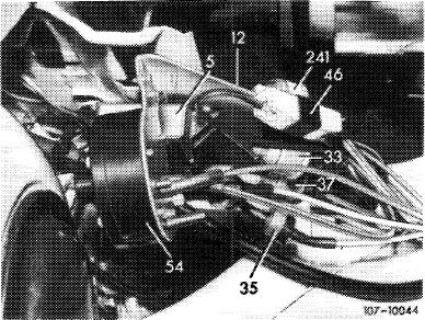
Solex carburetor 4 A 1
|
1976
|
 |
||
|
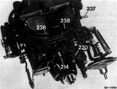
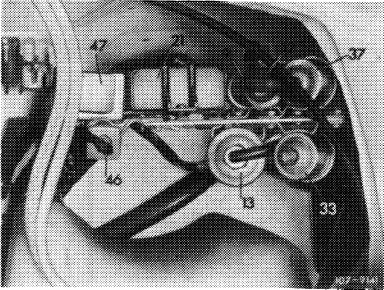
214 Float chamber vent valve (vacuum-controlled)
237 Vacuum connection for vacuum booster of EGR
238 Idle air combination jet
|
||||
|
|
||||
|
Solex carburetor 4 A 1
|
1976
|
 |
||
|
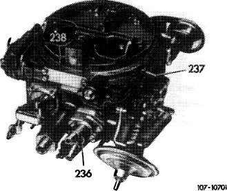
236 TN auxiliary choke
237 Vacuum connection for vacuum booster of EGR
238 Idle air combination jet
|
||||
|
|
||||
|
07.2.2 la-090/1
|
||||
|
|
||||
|
|
||||||
|
Solex carburetor 4 A 1
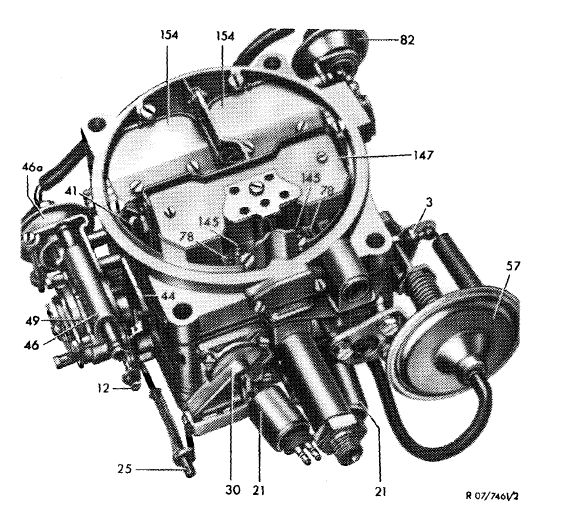
|
1973/74
|
 |
||||
|
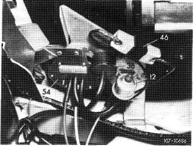
3 Throttle valve lever
12 Cold starting speed adjusting screw
21 Idle mixture cutoff valves
25 Adjusting nut accelerating pump
30 Accelerating pump cover
41 Choke rod
44 Fast idle cam
46 Choke housing
46a Vacuum control unit for automatic choke
49 Choke cover
57 Vacuum governor
78 Idle air jets
82 Vacuum control unit – air valve
damper stage II 145 Air correction jets stage I 147 Choke valve 154 Air valves stage II
|
||||||
|
|
||||||
|
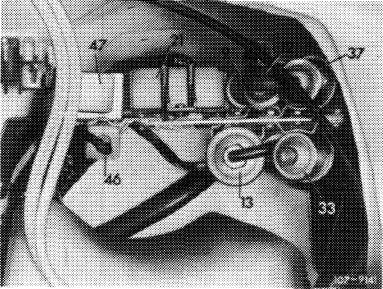
Solex carburetor 4 A 1 (@) California 1974
3 Throttle valve lever
12 Cold starting speed adjusting screw
21 Idle mixture cutoff valves
25 Adjusting nut accelerating pump
30 Accelerating pump cover
44 Fast idle cam
49 Choke cover
57 Vacuum governor
78 Idle air jets
82 Vacuum control unit — air valve
damper stage II
147 Choke valve
154 Air valves stage II
214 Float chamber vent valve
|
 |
|||||
|
|
||||||
|
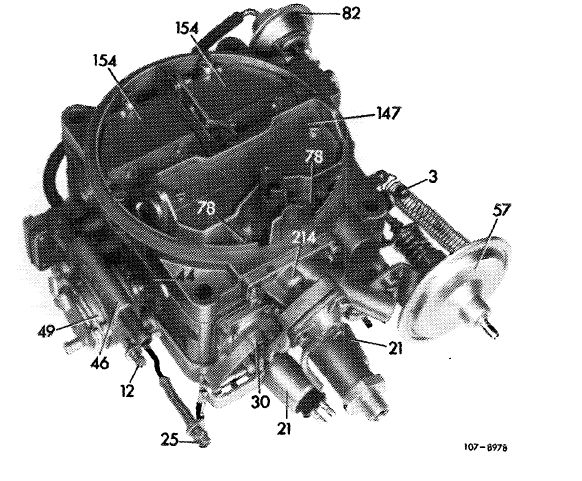
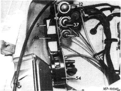
Solex carburetor 4 A 1 (@) 1975/76
|
 |
|||||
|
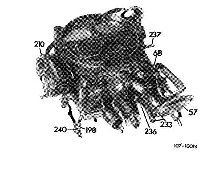
57 198 210 214 233 236 237
240
|
Vacuum governor
Actuating lever – accelerating pump
Pulldown cover
Float chamber vent valve
Coolant connection for TN starter
TN starter (thermostatically controlled bypass choke)
Vacuum connection for vacuum booster of EGR
(Venturi connection)
Plastic guide piece
|
|||||
|
07.2.2 la-090/2
|
||||||
|
|
||||||
|
|
||||||||||||||||||||||||||||||||||||||||||||||||||||||||||||||||||||||||||||||||||||||||||||||
|
The Solex carburetor 4 A 1 comprises 4 main components which are screwed to each other.
— carburetor cover
— carburetor housing
— throttle valve section
— starting device (choke)
|
||||||||||||||||||||||||||||||||||||||||||||||||||||||||||||||||||||||||||||||||||||||||||||||
|
|
||||||||||||||||||||||||||||||||||||||||||||||||||||||||||||||||||||||||||||||||||||||||||||||
|
Stage I is designed on the principle of Zenith carburetor:
— variable vacuum in mixing chamber
— main jet without change of cross section
|
||||||||||||||||||||||||||||||||||||||||||||||||||||||||||||||||||||||||||||||||||||||||||||||
|
|
||||||||||||||||||||||||||||||||||||||||||||||||||||||||||||||||||||||||||||||||||||||||||||||
|
Stage II operates on principle of Stromberg carburetor (constant pressure principle):
— constant vacuum in mixing chamber by means of an air valve constantly adapted to respective air flow
— main jets with variable cross section via needle control
|
||||||||||||||||||||||||||||||||||||||||||||||||||||||||||||||||||||||||||||||||||||||||||||||
|
|
||||||||||||||||||||||||||||||||||||||||||||||||||||||||||||||||||||||||||||||||||||||||||||||
 |
||||||||||||||||||||||||||||||||||||||||||||||||||||||||||||||||||||||||||||||||||||||||||||||
|
|
||||||||||||||||||||||||||||||||||||||||||||||||||||||||||||||||||||||||||||||||||||||||||||||
|
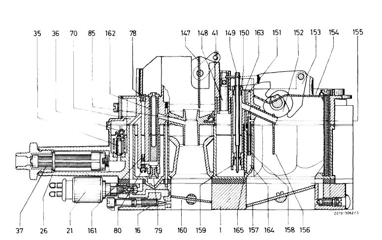
Baffle plate
Throttle valve stage II
Riser — bypass system stage II
Needle-controlled main jet stage II
Throttle valve stage I
Idle speed fuel jet
Mixing tube stage I
Vent bore — reserve chamber
Reserve chamber stage 11
Feed bore — reserve chamber
|
|||||||||||||||||||||||||||||||||||||||||||||||||||||||||||||||||||||||||||||||||||||||||||||
|
|
||||||||||||||||||||||||||||||||||||||||||||||||||||||||||||||||||||||||||||||||||||||||||||||
|
07.2.2 la-090/3
|
||||||||||||||||||||||||||||||||||||||||||||||||||||||||||||||||||||||||||||||||||||||||||||||
|
|
||||||||||||||||||||||||||||||||||||||||||||||||||||||||||||||||||||||||||||||||||||||||||||||
|
|
|||||||||||||||||||||||||||||||||||||||||||||||||||||
|
B. Float
|
|||||||||||||||||||||||||||||||||||||||||||||||||||||
|
|
|||||||||||||||||||||||||||||||||||||||||||||||||||||
|
The float is centrally located between the four mixing chambers. The float needle seat is pressed into carburetor housing. The needle is positively controlled. The fuel intake connection is provided with a filter.
|
|||||||||||||||||||||||||||||||||||||||||||||||||||||
|
|
|||||||||||||||||||||||||||||||||||||||||||||||||||||
|
 |
||||||||||||||||||||||||||||||||||||||||||||||||||||
|
|
|||||||||||||||||||||||||||||||||||||||||||||||||||||
|
Float chamber vent system
The float chamber must be vented to provide the pressure difference between fuel level and mixture outlet. The fuel flows out under the influence of the pressure difference between float chamber and mixture outlet. The carburetor is vented internally and externally. The external venting is operative when the engine is stopped, the internal venting when the engine is running.
|
|||||||||||||||||||||||||||||||||||||||||||||||||||||
|
|
|||||||||||||||||||||||||||||||||||||||||||||||||||||
|
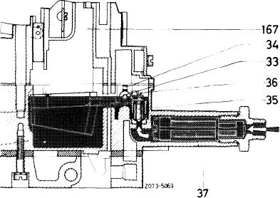
With the ignition switched on, the switchover valve for float chamber external venting is energized and switches.
|
 |
||||||||||||||||||||||||||||||||||||||||||||||||||||
|
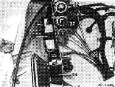
Model
© 1976
© 1975/76
37 Switchover valve
|
|||||||||||||||||||||||||||||||||||||||||||||||||||||
|
|
|||||||||||||||||||||||||||||||||||||||||||||||||||||
|
07.2.2 la-090/4
|
|||||||||||||||||||||||||||||||||||||||||||||||||||||
|
|
|||||||||||||||||||||||||||||||||||||||||||||||||||||
|
|
|||
|
Model 114 (@) California 1974 37 Switchover valve
|
 |
||
|
|
|||
|
Model 114 (usa) 1975/76 37 Switchover valve
|
 |
||
|
|
|||
|
For the national version (T)1976 and @) 1975/76 the float chamber vent valve is provided with a vacuum upon starting and will switch to „internal venting”.
For the national version (usa) California 1974 the float chamber vent valve is already provided with a vacuum from a vacuum reservoir with the engine stopped and the ignition switched on. The system switches to „internal venting”.
|
 |
||
|
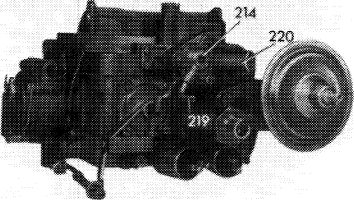
214 Float chamber vent valve
219 Vacuum connection
220 Negative vent connection
|
|||
|
|
|||
|
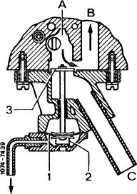
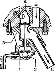
Float chamber, internally vented
A Duct from air filter clean air end
1 Diaphragm
2 Compression spring
3 Valve plate
|
 |
||
|
|
|||
|
07.2.2 la-090/5
|
|||
|
|
|||
|
|
|||
|
In dependence of the throttle valve position of stage I of the carburetor, the diaphragm of the intake valve is activated by a vacuum and the draw-off valve (purge valve) will switch.
|
107-8974
|
||
|
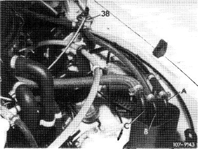
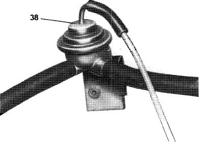
38 Draw-off valve (purge valve)
|
|||
|
|
|||
|
The intake pipe vacuum will now draw the stored vapors from charcoal canister by way of the draw-off valve and a connection on carburetor into intake pipe for combustion.
|
 |
||
|
38 Draw-off valve (purge valve)
A Negative tank vent connection
B Draw-off valve connection
C Float chamber positive vent valve connection
|
|||
|
|
|||
|
When the ignition is switched off, the switchover valve is de-energized and will switch. The vacuum in the diaphragm chamber is exhausted and the float chamber vent valve will switch to „external venting”.
|
 |
||
|
Float chamber, externally vented
B Duct from float chamber C Duct to atmosphere
|
|||
|
|
|||
|
To prevent the float chamber vent valve to switch to external venting at low intake pipe vacuum (e.g. during acceleration or when driving at full throttle), a check valve is installed in vacuum line.
|
|||
|
|
|||
|
07.2.2 la-090/6
|
|||
|
|
|||
|
|
|||
|
C. Idle speed
|
|||
|
|
|||
|
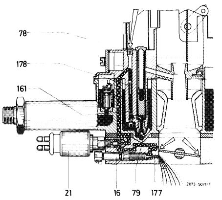
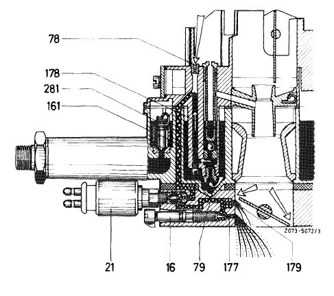
The idle speed system is associated with stage I. The fuel required for idle speed is taken from main jet system behind main jets (dependent idle speed system). The fuel flows via main jet through idle speed fuel jet.
The required air is fed via the idle speed air nozzle and mixes with the intake fuel. This idle speed emulsion (initial mixture) flows out below throttle valve. Its quantity can be changed by the idle speed mixture adjusting screw.
The idle speed mixture is formed by the initial mixture and the air entering through annular gap of throttle valves.
|
|||
|
|
|||
|
16 Idle speed mixture adjusting screw
21 Idle speed shutoff valve
78 Idle speed air jet
79 Main jet stage I 161 Idle speed fuel jet
177 Idle speed mixture outlet bore
178 Idle speed fuel duct
|
 |
||
|
|
|||
|
Idle speed shutoff valve
The idle speed mixture ducts are provided with screwed-in shutoff valves in front of idle speed mixture adjusting screws.
With the ignition switched on, the shutoff valves are energized and are open. When the ignition is switched off, the shutoff valves will be de-energized and will close the idle speed mixture flow holes by means of their spring-loaded sealing cones, so that any afterrunning of engine is prevented.
|
|||
|
|
|||
|
D. Bypass carburetor stage
|
|||
|
|
|||
|
To guarantee perfect transition from idle speed to main jet system of stage I, bypass bores are provided above idle speed mixture outlet bores, covered by the throttle valves. When the throttle valves are opened, these calibrated bores are exposed. The resulting vacuum will draw off additional fuel emulsion through those bores.
|
|||
|
|
|||
|
07.2.2 la-090/7
|
|||
|
|
|||
|
|
|||
|
16 Idle speed mixture adjusting screw
21 Idle speed shutoff valve
78 Idle speed air jet
79 Main jet stage I 161 Idle speed fuel jet
177 Idle speed mixture outlet bore
178 Idle speed fuel duct
179 Bypass bores stage I
|
 |
||
|
|
|||
|
E. Acceleration
|
|||
|
|
|||
|
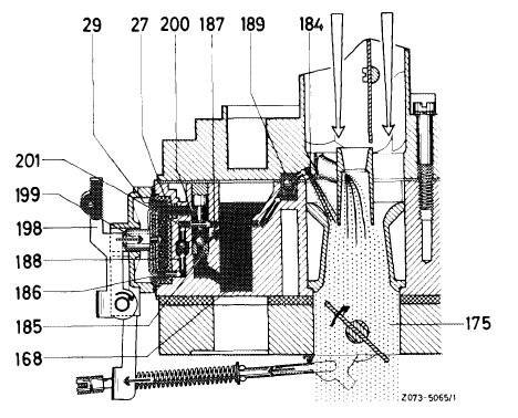
To guarantee adaptation of mixture quantity to heavily increasing air flow during sudden acceleration, an accelerating pump will be required.
The accelerating pump is a mechanically actuated diaphragm pump. The fuel is injected through calibrated bores or jets in carburetor cover.
During the suction stroke of the diaphragm, the fuel is sucked from float chamber through suction valve into pump chamber. The pump chamber is lined by a plastic shell for thermal insulation. Any vapor bubbles will escape through a vent bore in float chamber.
During pressure stroke of diaphragm, the fuel is injected into mixing chambers of stages I via the pressure valves and the calibrated injection bores. The two pressure valves prevent the penetration of air into pump system during suction stroke.
Note: To enrich the mixture, additional fuel is drawn from pump system (neutral pump) in dependence of the vacuum in the mixing chamber.
|
|||
|
|
|||
|
27 Plastic shell
29 Diaphragm
184 Calibrated injection bore
185 Suction valve
186 Pump chamber
187 Vent bore
188 Pressure valve
189 Pressure valve
|
 |
||
|
|
|||
|
07.2.2 la-090/8
|
|||
|
|
|||
|
|
|||
|
F. Main jet system carburetor stage I
|
|||
|
|
|||
|
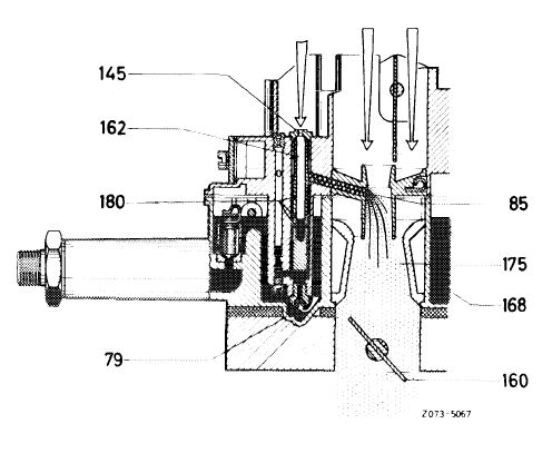
Main jet system
The fuel flows from float chamber through main jets into the mixing tubes. When the air flow rate (vacuum) is adequately high, the fuel is drawn off into the mixing chambers.
At increasing speed, the fuel level in mixing tubes will drop and will expose the compensating air bores one after the other. The compensating air flowing in through air correction jets mixes with the fuel into an emulsion and prevents excessive enrichment.
|
|||
|
|
|||
|
79 Main jet stage I
85 Pre-atomizer with mixture outlet arm
145 Air correction jet stage I
162 Mixing tube stage I
168 Float chamber
180 Compensating bores
|
 |
||
|
|
|||
|
G. Bypass carburetor stage II
|
|||
|
|
|||
|
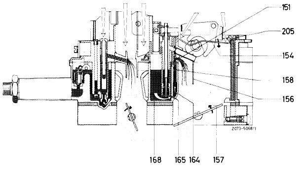
To guarantee a lag-free transition (bypass) from stage I up to start of main jet system of stage II, bypass bores are located below air valves.
When the air valves are opening, fuel is drawn from reserve chambers through the riser pipes. The fuel flows to the reserve chambers through calibrated bores which are dimensioned in such a manner that only the follow-up fuel can be drawn from empty reserve chambers. This will limit a quantity available for enrichment. The mixture is guided by the baffle plates into the gap of the opening throttle valves.
|
|||
|
|
|||
|
07.2.2 la-090/9
|
|||
|
|
|||
|
|
||||
|
151 Bypass bore stage II
154 Air valve
156 Baffle plate
158 Riser bypass system stage II
164 Reserve chamber
165 Calibrated feed bore 168 Float chamber
|
 |
|||
|
205 Stop for air valve carburetor stage II
|
||||
|
|
||||
|
Dashpot for air valve carburetor stage II
The vacuum-controlled dashpot serves the purpose of preventing the sudden opening of the air valves. The dashpot is provided with a vacuum by way of a vacuum line which opposes the vacuum at the air valve.
The location of the vacuum tapping bore for the dashpot, as well as the dimensions of the diaphragm in the dashpot are designed in such a manner that the vacuum effective at the air valve is always able to open the valves.
|
||||
|
|
||||
|
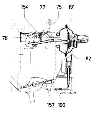
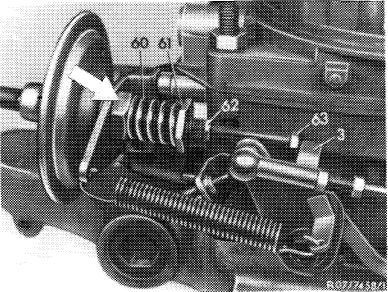
75 Restoring spring
82 Dashpot — air valves
154 Air valve stage II
190 Vacuum tapping bore
191 Diaphragm
|
 |
|||
|
|
||||
|
Note: During acceleration, the air flaps must be opened under delay so that enough fuel is available for a good bypass (fuel column will accelerate slower than air column) to eliminate faults when passing from carburetor stage I to carburetor stage II.
The dashpot serves the same purpose as that in Stromberg carburetor (accelerating pump effect). The dashpot acts in direction of restoring spring on air valves of stage II and only during acceleration, but not when the throttle valve position remains the same.
|
||||
|
|
||||
|
07.2.2 la-090/10
|
||||
|
|
||||
|
|
|||
|
H. Main jet system carburetor stage II
|
|||
|
|
|||
|
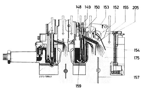
When the throttle valves are opening, the vacuum in mixing chambers will increase. The eccentrically supported air valves are opened by this vacuum against the force of the restoring spring. The opening of the air valves makes the intake cross section larger and reduces the vacuum until an equilibrium is established between the vacuum on the one hand and the spring-loaded air valves on the other. As a result, the air valves will take a position which is in a given ratio to the throttle valve opening and to the air flow rate. Consequently, the vacuum at fuel outlet will remain approximately constant.
When the air valves are opening, the cam will simultaneously actuate the transmitting lever, the guide pin and the jet needles, with the latter releasing a pertinent annular gap in main jet with their conical section.
The correction air flows in via the annular gap between jet needle and air correction jet and mixes with the fuel into an emulstion which is drawn off into the mixing chambers via the outlet arms.
|
|||
|
|
|||
|
148 Guide pin
149 Jet needle stage II
150 Air correction jet stage II
152 Cam
153 Transmitting lever
154 Air valve stage II
155 Fuel outlet arm
159 Needle-controlled main jet stage II
175 Mixing chamber
205 Fuel outlet
|
 |
||
|
|
|||
|
I. Starting device (choke)
|
|||
|
|
|||
|
The starting device (choke) is controlled by means of the electrically and coolant-heated bimetallic spring in choke cover. The coolant heating is required to prevent re-engagement of choke when the engine is shut off for a short period.
The choke engages automatically on cold engine when the accelerator pedal is actuated once. The choke valve is closed by the bimetallic spring by way of a driver and the choke rod. The fast idle cam with the counterweight is simultaneously turned to cold starting position. This will place the throttle valve lever on the topmost step of the fast idle cam and the throttle valves of stage I are opened by a given angle.
|
|||
|
|
|||
|
07.2.2 la-090/11
|
|||
|
|
|||
|
|
||||
|
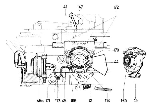
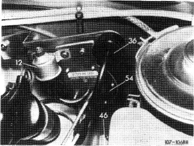
12 Cold starting speed
adjusting screw 41 Choke rod
44 Fast idle cam with coutnerweight
45 Detent lever stage II
46 Vacuum control unit housing 46a Dashpot (pulldown)
49 Choke cover 147 Choke valve 166 Throttle valve stop for choke
169 Bimetallic spring
170 Drive lever — choke valve
171 Throttle valve shaft stage II
172 Coolant connection
173 Connecting rod (pulldown)
174 Transmitting lever — accelerating pump
|
 |
|||
|
|
||||
|
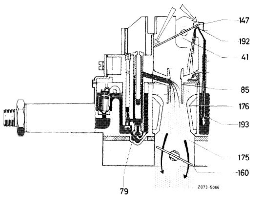
The closed choke valve will increase the vacuum in the mixing chambers when the engine is started to the extent that fuel is drawn from main jet system. This vacuum will also act against closed choke valve and will open that valve against the force of the bimetallic spring to the extent that the air required for the starting mixture can flow in.
Additional fuel is drawn in via the riser pipes of the start enrichment system until the choke valve is slightly opened (choke valve gap). The result is an initially rich starting mixture which permits the engine to fire reliably even at low temperatures.
|
||||
|
|
||||
|
41 Choke rod
79 Main jet stage I
85 Pre-atomizer with mixture outlet arm
147 Choke valve
160 Throttle valve stage I
175 Mixing chamber
176 Venturi
192 Starting mixture enrichment bore
193 Riser pipe-starting mixture enrichment
|
 |
|||
|
|
||||
|
Following firing of the engine the choke valve is opened to a given gap dimension (choke valve gap) by the vacuum diaphragm of the choke via the connecting rod and the drive lever. The increasing heat of the bimetallic spring will open the choke valve still further so that at 70—75 °C coolant temperature the choke is completely switched off.
The throttle valve of stage II is locked by the detent lever. Unlocking will occur only when the choke is completely switched off, i.e. when the choke valve is fully opened by the drive pin of the fast idle cam.
|
||||
|
|
||||
|
07.2.2 la-090/12
|
||||
|
|
||||
|
|
||||||||||||||||||||||||||||||||||||||||||||||||||||||||||||||||||||||||
|
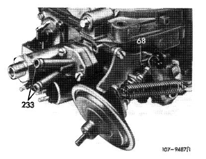
Thermostatically controlled auxiliary bypass choke (TN choke)
The thermostatically controlled auxiliary bypass choke is installed together with the following carburetors:
CD 1976 © 1976 @> 1975/76
Significance of designation „TN”:
T = temperature-controlled N = bypass
|
||||||||||||||||||||||||||||||||||||||||||||||||||||||||||||||||||||||||
|
|
||||||||||||||||||||||||||||||||||||||||||||||||||||||||||||||||||||||||
|
To improve the warming-up characteristics, the warming-up mixture is guided into the intake pipe in dependence of the coolant temperature, while bypassing the throttle valve.
|
 |
|||||||||||||||||||||||||||||||||||||||||||||||||||||||||||||||||||||||
|
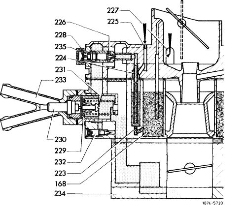
233 Thermostatically controlled auxiliary bypass choke (TN choke)
|
||||||||||||||||||||||||||||||||||||||||||||||||||||||||||||||||||||||||
|
|
||||||||||||||||||||||||||||||||||||||||||||||||||||||||||||||||||||||||
|
The vacuum in intake pipe serves to draw fuel from float chamber by way of the starting fuel jet. The fuel will move upwards in mixing tube and will be mixed with air from the starting air jet into a fuel-air mixture. This fuel-air mixture is mixed with additional air from air duct at outlet bores. The mixing ratio is set by the manufacturer by means of the temperature-controlled mixture adjusting screw (TN mixture adjusting screw).
|
||||||||||||||||||||||||||||||||||||||||||||||||||||||||||||||||||||||||
|
|
||||||||||||||||||||||||||||||||||||||||||||||||||||||||||||||||||||||||
|
 |
|||||||||||||||||||||||||||||||||||||||||||||||||||||||||||||||||||||||
|
|
||||||||||||||||||||||||||||||||||||||||||||||||||||||||||||||||||||||||
|
|
|||
|
The mixture flowing to the intake pipe is metered by a control piston which is actuated in dependence of the coolant temperature by means of an expanding element. With increasing coolant temperature, the control piston will close the control window until it is completely closed at 70—75 °C. The choke is thereby switched off except for a very low amount of leak mixture, which flows to the intake pipe by way of the leak volume adjusting screw. The leak volume is set by the manufacturer.
The setting of the throttle valve required for a cold start is no longer made by means of the fast idle cam, but via the vacuum governor. For this reason, the adjusting screw for cold starting speed is no longer installed. The fast idle cam now controls only the unlocking of stage 11 which results in the complete opening of the choke valve.
|
|||
|
|
|||
|
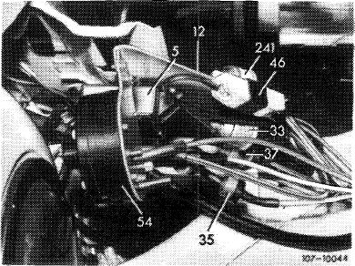
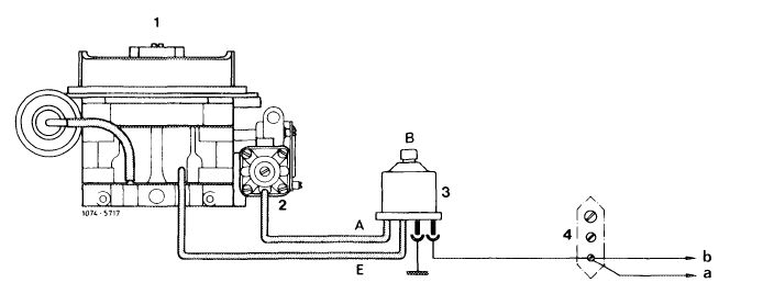
Switchover valve for pulldown delay (lag)
The switchover valve prevents the pulldown from pulling the starting valve immediately to a gap position during the starting procedure, since this might stop the engine immediately upon starting.
During the starting procedure (as long as the ignition key is in starting position) the choke provides the switchover valve in vacuum line to choke housing with control current via terminal 50. This will connect the vacuum chamber to the outside air (atmosphere).
When the ignition key moves back from its starting position, the switchover valve will switch over. This will provide the vacuum chamber in choke housing with a vacuum and the choke valve will be pulled to the specified gap.
|
|||
|
|
|||
 |
|||
|
|
|||
|
1 Solex carburetor 4 A
2 Choke housing
3 Switchover valve
4 Cable connector
|
A Outlet (to choke housing — red line)
B Connection to atmosphere
E Inlet (from carburetor — white line)
a To ignition starter switch
b To starter terminal 50
|
||
|
|
|||
|
The carburetor is provided with an orifice (throttle) in vacuum connecting pipe. As a result, the choke valve will not be opened suddenly, but is pulled to choke valve gap under delay.
|
|||
|
|
|||
|
07.2.2 la-090/14
|
|||
|
|
|||
|
|
|||||||||||||||||||||||||||||||||||||||||||||||||||||
|
Thermo delay valve for choke
|
1976 only)
|
 |
|||||||||||||||||||||||||||||||||||||||||||||||||||
|
The thermo delay valve opens the choke valve upon firing of engine under delay in dependence of the temperature. The valve is located in vacuum line to pulldown.
|
|||||||||||||||||||||||||||||||||||||||||||||||||||||
|
|
|||||||||||||||||||||||||||||||||||||||||||||||||||||
|
254 Thermo delay valve
|
107-10706
|
||||||||||||||||||||||||||||||||||||||||||||||||||||
|
|
|||||||||||||||||||||||||||||||||||||||||||||||||||||
|
The thermo delay valve serves the purpose of pulling the choke valve at temperatures above approx. upon firing of engine not immediately to the required choke valve gap, but under delay.
|
12 °C
|
||||||||||||||||||||||||||||||||||||||||||||||||||||
|
|
|||||||||||||||||||||||||||||||||||||||||||||||||||||
|
At temperatures below approx. — 12 °C there is no delay under influence of thermo delay valve. At low outside temperatures, the vacuum generated by the engine is relatively low. If this vacuum would be additionally throttled, the choke valve would be opened too slowly and the warming-up mixture would become too rich, i.e. the spark plugs would soot up and misfiring would result.
|
|||||||||||||||||||||||||||||||||||||||||||||||||||||
|
|
|||||||||||||||||||||||||||||||||||||||||||||||||||||
|
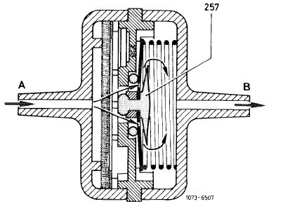
Ambient temperature above approx. — 12 °C
The vacuum generated by the engine is established via connection (A), filter, sintered metal disc up to diaphragm of choke. The throttle effect of the sintered metal disc will pull (open) the choke valve under delay.
|
 |
||||||||||||||||||||||||||||||||||||||||||||||||||||
|
|||||||||||||||||||||||||||||||||||||||||||||||||||||
|
|
|||||||||||||||||||||||||||||||||||||||||||||||||||||
|
A rubber check valve is installed to make sure that the choke valve returns immediately and without delay into closing position prior to a possible attempt for a re-start.
If the engine stops after starting, the vacuum in choke housing will open the check valve. The diaphragm chamber in choke housing will be energized, the choke valve will close immediately.
|
 |
||||||||||||||||||||||||||||||||||||||||||||||||||||
|
|
|||||||||||||||||||||||||||||||||||||||||||||||||||||
|
07.2.2 la-090/15
|
|||||||||||||||||||||||||||||||||||||||||||||||||||||
|
|
|||||||||||||||||||||||||||||||||||||||||||||||||||||
|
|
|||
|
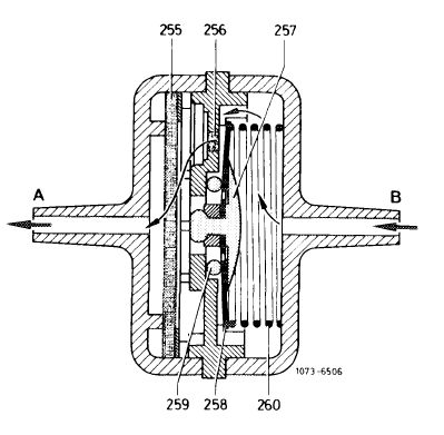
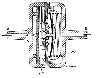
Ambient temperature below approx. — 12 °C
Below approx. — 12 °C the bimetallic valve plate will snap over and will lift off from rubber sealing ring, so that the vacuum can act unthrottled on diaphragm of automatic choke. The sintered metal disc will be bypassed.
|
 |
||
|
258 Bimetallic valve plate
259 Rubber sealing ring
|
|||
|
|
|||
|
Attention!
When installing the thermo delay valve, pay attention to direction of installation.
1. Thermo delay valve with arrow: Arrow in direction of throttle valve section
2. Thermo delay valve in two colors:
Black side in direction of throttle valve section
|
|||
|
|
|||
|
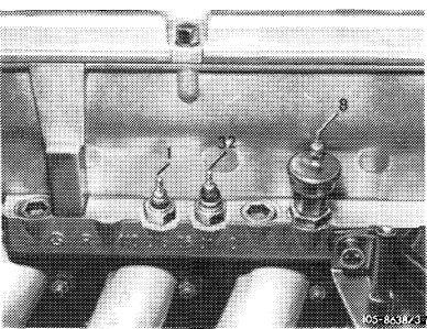
Choke cover-stepped heater
To improve warming-up characteristics, the choke cover of the automatic choke is heated in two steps. Below 17 °C oil temperature at reduced output, above 17 °C oil temperature the choke cover is heated at normal capacity.
Below 17 °C oil temperature the oil temperature switch (7) in oil filter housing is closed, the relay will switch, so that the current flows across pre-resistor.
|
 |
||
|
7 Oil temperature switch 17 °C
|
|||
|
|
|||
|
The oil temperature switch (7) will open above 17 °C oil temperature and thereby interrupt the ground connection to relay. The relay switches over, so that the current will flow directly to choke cover while bypassing the pre-resistor.
|
 |
||
|
Model 116 ©1976, (us
5 Relay 46 Resistor for choke cover-stepped heater
|
|||
|
|
|||
|
07.2.2 la-090/16
|
|||
|
|
|||
|
|
|||
|
Model 114 (@> California 1974
21 Relay
46 Resistor for choke cover-stepped heater
|
 |
||
|
|
|||
|
Model 114 ® 1975/76
5 Relay 46 Resistor for choke cover-stepped heater
|
 |
||
|
|
|||
|
Model 114
46 Resistor for choke cover-stepped heater
|
 |
||
|
|
|||
|
Model 116
46 Resistor for choke cover-stepped heater
|
 |
||
|
|
|||
|
07.2.2 la-090/17
|
|||
|
|
|||
|
|
|||
|
As a result of the electric coupling of temperature switch 17 °C (7) and temperature switch 100 °C (8) the reduced heater output will also become effective at coolant temperatures above 100 °C, but the automatic choke will then no longer be affected.
|
 |
||
|
7 Oil temperature switch 17 °C
|
|||
|
|
|||
|
8 Coolant temperature switch 100 °C
|
 |
||
|
|
|||
|
J. Vacuum governor
|
 |
||
|
The vacuum governor is installed on all Solex carburetors 4 A 1 as standard equipment and serves the purpose of stabilizing the idle speed when the engine is loaded by the additional engagement of auxiliary units or by shifting into a driving position.
At idle speed of the engine, the intake pipe vacuum will pull back the diaphragm by means of the adjusting screw. If the idling speed drops as a result of the engine load, the effective vacuum will also drop and the compression spring can now adjust the throttle valve still further by means of the adjusting screw.
On Solex carburetors 4 A 1 with thermostatically controlled bypass choke (TN choke) the arrangement of the vacuum governor has been changed. Operation is as described above with the following difference. The throttle valve is no longer moved into starting position as before by means of the fast idle cam, but via the vacuum governor. During the warming-up period, the throttle valve lever rests against idle speed stop. When a driving position is engaged or when the power steering is operating, the vacuum governor can lift the throttle valve slightly when the engine speed
drops.
Carburetor with thermostatically controlled
bypass choke (TN choke)
|
|||
 |
|||
|
|
|||
|
07.2.2 la-090/18
|
|||
|
|
|||
|
|
|||||
|
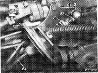
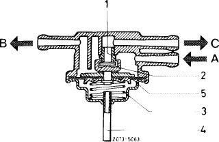
K. Fuel return valve
|
|||||
|
|
|||||
|
The fuel return valve is located in fuel feed line in front of carburetor and is connected to fuel tank by means of a return line.
At idle and in partial load range the diaphragm is pulled down against the spring by the high vacuum and the valve will open. The excess fuel flows back into fuel tank. This fuel circulation will continuously feed relatively cool fuel to the carburetor and vapor lock will be checked.
|
|||||
|
|
|||||
|
1 Valve seat
2 Valve
3 Spring
4 Vacuum connection
5 Diaphragm
|
A Fuel feed from delivery pump B Fuel feed to carburetor C Fuel return to fuel tank
|
 |
|||
|
|
|||||
|
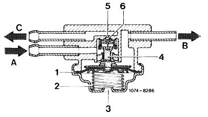
Fuel return valve with pressure control ((V) 1976 only)
The fuel return valve is simultaneously designed as a fuel pressure regulator. Regulation of fuel return quantity and fuel pressure to approx. 0.2 bar (gauge pressure) is effected by means of a spring-loaded valve. Fuel level fluctuations will be widely avoided. The former vacuum connection to fuel return valve is no longer in place.
|
|||||
|
|
|||||
|
1
2 3 4 5 6
|
Diaphragm Spring Vent bore Control cone Throttle bore Return valve
|
A Fuel feed from delivery pump B Fuel feed to carburetor C Fuel return to fuel tank
|
 |
||
|
|
|||||
|
07.2.2 la-090/19
|
|||||
|
|
|||||