Removal and installation of intermediate gear shaft
|
|
||||||||||||||||||||||||||||||||||||||||||||||||||||||||||||||||
|
05-412 Removal and installation of intermediate gear shaft
|
||||||||||||||||||||||||||||||||||||||||||||||||||||||||||||||||
|
|
||||||||||||||||||||||||||||||||||||||||||||||||||||||||||||||||
|
Tightening torques
|
Nm
|
|||||||||||||||||||||||||||||||||||||||||||||||||||||||||||||||
|
|
||||||||||||||||||||||||||||||||||||||||||||||||||||||||||||||||
|
||||||||||||||||||||||||||||||||||||||||||||||||||||||||||||||||
|
|
||||||||||||||||||||||||||||||||||||||||||||||||||||||||||||||||
|
Chain tensioner holder
|
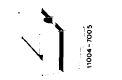 |
110 589 02 31 00
|
||||||||||||||||||||||||||||||||||||||||||||||||||||||||||||||
|
|
||||||||||||||||||||||||||||||||||||||||||||||||||||||||||||||||
|
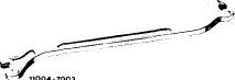
Impact extractor for bearing pin (basic unit)
|
 |
116 589 20 33 00
|
||||||||||||||||||||||||||||||||||||||||||||||||||||||||||||||
|
|
||||||||||||||||||||||||||||||||||||||||||||||||||||||||||||||||
|
||||||||||||||||||||||||||||||||||||||||||||||||||||||||||||||||
|
|
||||||||||||||||||||||||||||||||||||||||||||||||||||||||||||||||
|
Valve adjusting wrench 17 mm
|
 |
110 589 01 01 00
|
||||||||||||||||||||||||||||||||||||||||||||||||||||||||||||||
|
|
||||||||||||||||||||||||||||||||||||||||||||||||||||||||||||||||
|
Wrench socket 10 mm 1/2″ square, 140 mm long
|
 |
000 589 05 07 00
|
||||||||||||||||||||||||||||||||||||||||||||||||||||||||||||||
|
Wrench socket 27 mm, 1/2″ square to turn engine
|
001 589 65 09 00
|
|||||||||||||||||||||||||||||||||||||||||||||||||||||||||||||||
|
|
||||||||||||||||||||||||||||||||||||||||||||||||||||||||||||||||
|
05.2-412/1 F3
|
||||||||||||||||||||||||||||||||||||||||||||||||||||||||||||||||
|
|
||||||||||||||||||||||||||||||||||||||||||||||||||||||||||||||||
|
|
|||
|
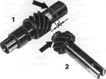
IViOte
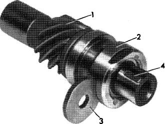
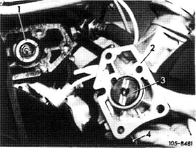
The oil pump drive consists of intermediate gear shaft (1) and helical gear shaft (2), and must always be replaced in pairs (05—410).
For repairs, install oil pump drive part no. 110 050 02 06.
Intermediate gear (1): 9 teeth, groove (arrow). Dimension A = 5 mm.
Helical gear (2): 12 teeth, groove (arrow), standard installation refer to 05—410.
|
 |
||
|
|
|||
|
1O5-1O443/2
|
|||
|
|
|||
|
Removal
|
 |
||
|
1 Partially drain coolant. Remove fan and radiator.
|
|||
|
2 Remove helical gear shaft (05-410).
|
|||
|
3 Remove vibration damper and pulley (03—340).
|
|||
|
|
|||
|
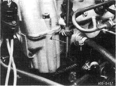
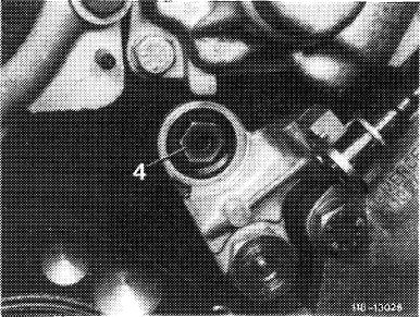
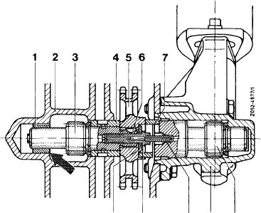
4 Unscrew plug in crankcase and remove oil pressure relief valve (4).
|
 |
||
|
|
|||
|
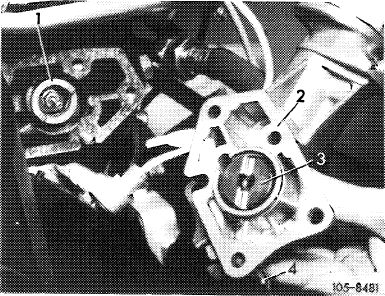
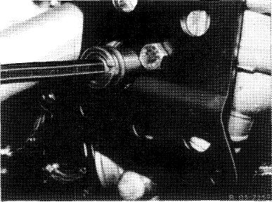
5 Remove distributor housing (2) and take off dog (1). Do not take distributor drive shaft (3) out of distributor housing (2).
|
 |
||
|
|
|||
|
05.2-412/2 F2
|
|||
|
|
|||
|
|
|||
|
6 Remove screw (15) and washer (16).
|
 |
||
|
|
|||
|
7 Remove chain tensioner (05—310).
|
 |
||
|
|
|||
|
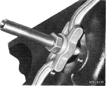
8 Relief tension on timing chain at intermediate wheel by turning crankshaft backwards briefly. Remove chain lock screw.
9 Knock in intermediate wheel shaft (3) and at the same time pull off intermediate wheel (1) forward.
|
 |
||
|
|
|||
|
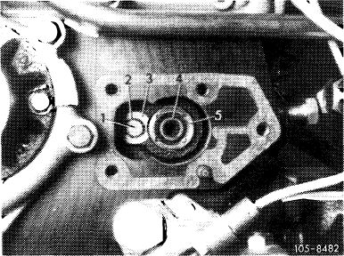
10 Place intermediate wheel down until bolt (1) is accessible.
11 Cover bottom of chain case with a cloth.
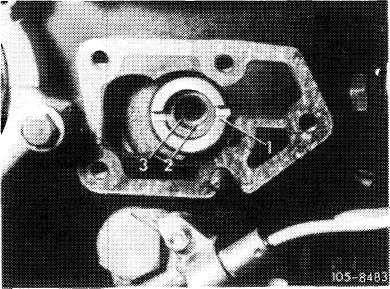
12 Unscrew bolt (1). Remove circlip (2) and lock washer (3).
|
 |
||
|
|
|||
|
05.2-412/3
|
|||
|
|
|||
|
|
||||
|
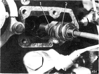
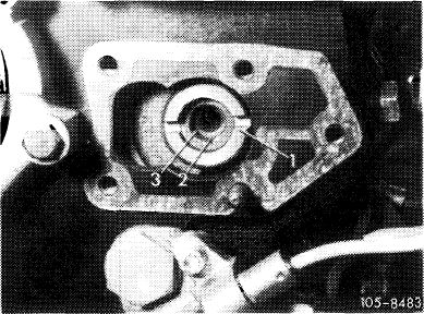
13 Pull out intermediate wheel shaft (1) and bearing sleeve (2) with a M 8 bolt.
|
 |
|||
|
|
||||
|
14 Pull out rear bearing bushing with an internal claw extractor.
|
 |
|||
|
|
||||
|
Installation
|
 |
|||
|
15 Knock in rear bearing bushing (1) with groove facing up using a 17 mm dia. stepped mandrel until it is flush with crankcase (arrow).
|
||||
|
|
||||
|
12 11
|
10 9 8
|
|||
|
|
||||
|
16 Install new intermediate wheel shaft (1) with woodruff key (4), bearing bushing (2) and lock washer (3).
|
 |
|||
|
|
||||
|
105-10442
|
||||
|
|
||||
|
05.2-412/4
|
||||
|
|
||||
|
|
|||
|
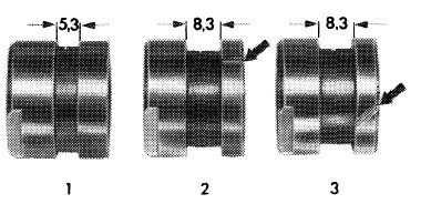
Attention!
Use bearing bushing (2) part no. 110 052 00 06 with straight splash groove only.
|
|||
|
|
|||
|
Front bearing bushing
Version 2 : valid
Version 1 and 3 : not valid
|
 |
||
|
|
|||
|
105-8287
|
|||
|
|
|||
|
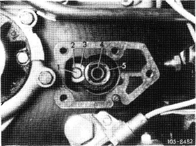
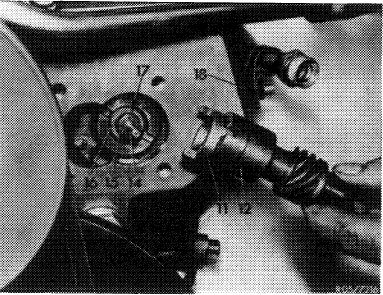
17 Install bolt (1) with circlip (2) and washer (3), and tighten.
|
 |
||
|
|
|||
|
18 Position intermediate wheel on intermediate wheel shaft and pull on with a M 8 bolt. In so doing the woodruff key must be aligned with groove in intermediate wheel. Teeth of intermediate wheel must grasp timing chain.
|
 |
||
|
|
|||
|
19 Move chain tensioner to assembly position and install (05-310).
|
 |
||
|
Chain tensioner in assembly position
|
|||
|
|
|||
|
05.2-412/5 F2
|
|||
|
|
|||
|
|
|||
|
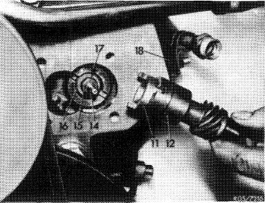
20 Install bolt (15) with oil tube (14) and washer (16), and torque to 25 Nm.
|
 |
||
|
|
|||
|
21 Place dog (1) on intermediate wheel and install distributor housing (2) with drive gear (3). Also fasten TDC pointer (4).
|
 |
||
|
|
|||
|
22 Set piston 1 at ignition TDC and install distributor.
23 Install new helical gear (4). Turn engine until oil pump drive shaft (9) engages in helical gear.
|
 |
||
|
|
|||
|
05.2-412/6 F3
|
|||
|
|
|||
|
|
||||
|
24 Knock in new cover (2) with an approx. 35 mm dia. sleeve.
25 Install intake manifold.
|
 |
|||
|
Attention!
Additionally install an oil pressure relief valve
114 180 02 15 with 5 bar gauge pressure into main oil
duct in cylinder crankcase together with oil pump
drive 110 050 02 06.
Standard installation refer to 18-020.
|
||||
|
|
||||
|
26 Install 5 bar oil pressure relief valve (4) without seal in main oil bore of crankcase and torque to 40 Nm.
27 Coat plug (5) with a sealing compound, install without seal and torque to 40 Nm.
|
 |
118-10386
|
||
|
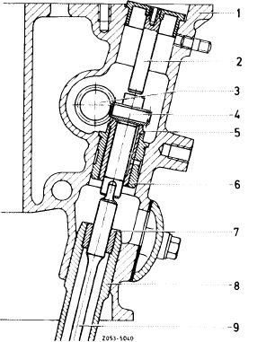
1 Plug
2 Oil bore plug
3 Aluminium seal
4 Oil pressure relief valve (5 bar)
5 Plug for oil pressure relief valve
|
||||
|
|
||||
|
28 Install vibration damper and pulley (03—340).
29 Install radiator and fan (20-420).
30 Check and adjust ignition timing (07.5—510).
|
||||
|
|
||||
|
05.2-412/7 F3
|
||||
|
|
||||