Removal and installation of guide wheel
|
|
||||||||||||||||||||||||||||||||||||||||||||
|
05—440 Removal and installation of guide wheel
|
||||||||||||||||||||||||||||||||||||||||||||
|
|
||||||||||||||||||||||||||||||||||||||||||||
|
Tightening torques
|
Nm
|
|||||||||||||||||||||||||||||||||||||||||||
|
|
||||||||||||||||||||||||||||||||||||||||||||
|
Cylinder head cover bolts and capped nuts
|
||||||||||||||||||||||||||||||||||||||||||||
|
|
||||||||||||||||||||||||||||||||||||||||||||
|
Ball locating ring in chain tensioner
|
25
|
|||||||||||||||||||||||||||||||||||||||||||
|
|
||||||||||||||||||||||||||||||||||||||||||||
|
Special tools
|
||||||||||||||||||||||||||||||||||||||||||||
|
|
||||||||||||||||||||||||||||||||||||||||||||
|
Impact extractor for bearing pin (basic unit)
|
 |
116 589 20 33 00
|
||||||||||||||||||||||||||||||||||||||||||
|
|
||||||||||||||||||||||||||||||||||||||||||||
|
Chain tensioner holder
|
110 589 02 31 00
|
|||||||||||||||||||||||||||||||||||||||||||
|
|
||||||||||||||||||||||||||||||||||||||||||||
|
||||||||||||||||||||||||||||||||||||||||||||
|
|
||||||||||||||||||||||||||||||||||||||||||||
|
Removal
|
||||||||||||||||||||||||||||||||||||||||||||
|
|
||||||||||||||||||||||||||||||||||||||||||||
|
1 Mark relation to timing chain and left camshaft sprocket with paint.
|
||||||||||||||||||||||||||||||||||||||||||||
|
|
||||||||||||||||||||||||||||||||||||||||||||
|
2 Remove chain tensioner or spring (05—310).
3 Remove sliding rail (2) in camshaft housing. This requires knocking out bearing pin with impact extractor (05-340).
|
 |
|||||||||||||||||||||||||||||||||||||||||||
|
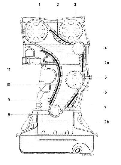
1 Exhaust camshaft sprocket 2-2b Sliding rail
3 Intake camshaft sprocket
4 Guide wheel
5 Locking screw
6 Intermediate wheel
7 Timing chain
8 Camshaft sprocket
9 Tensioning rail bearing pin
10 Tensioning rail
11 Hydraulic chain tensioner
|
||||||||||||||||||||||||||||||||||||||||||||
|
|
||||||||||||||||||||||||||||||||||||||||||||
|
05.2-440/1 F3
|
||||||||||||||||||||||||||||||||||||||||||||
|
|
||||||||||||||||||||||||||||||||||||||||||||
|
|
|||
|
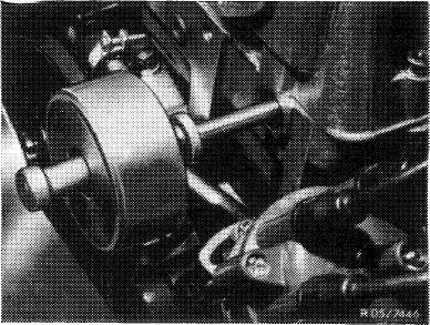
4 Hold guide wheel with a 5 mm dia. wire hook and knock out bearing pin with an impact extractor (10 mm bolt).
|
 |
||
|
|
|||
|
Installation
|
 |
||
|
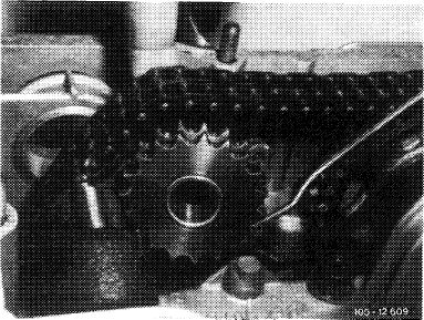
5 Guide in guide wheel with a 5 mm dia. wire hook, position correctly and knock in bearing pin with an impact extractor.
6 Install sliding rail in camshaft housing, noting marks on timing chain and left camshaft sprocket.
7 Set chain tensioner at assembly position and install, or install spring (05-310).
|
|||
|
|
|||
|
05.2-440/2
|
|||
|
|
|||