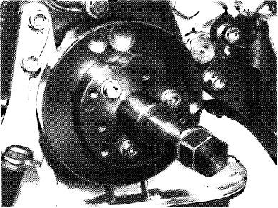
Removal and installation of crankshaft sprocket
|
|
||||
|
03—350 Removal and installation of crankshaft sprocket
|
||||
|
|
||||
|
Tightening torques
|
Nm
|
|||
|
|
||||
|
Bolt M 18 x 1.5 x 45 on crankshaft
|
400-450
|
|||
|
|
||||
|
Bolts and capped nuts for cylinder head cover
|
||||
|
|
||||
|
Special tools
|
||||
|
|
||||
|
Torque wrench 150-500 Nm (15-50 kpm), 3/4″ square
|
 |
001 589 31 21 00
|
||
|
|
||||
|
Socket 27 mm, 1/2″ square
|
 |
001 589 65 09 00
|
||
|
|
||||
|
Detent
|
 |
110 589 00 40 00
|
||
|
|
||||
|
Detent
|
 |
116 589 01 40 00
|
||
|
|
||||
|
Puller for balancing disc
|
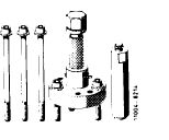 |
116 589 10 33 00
|
||
|
|
||||
|
Puller for spacing ring
|
 |
102 589 00 33 00
|
||
|
|
||||
|
Crankshaft sprocket extractor
|
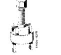 |
615 589 01 33 00
|
||
|
|
||||
|
Bearing pin impact extractor (basic unit)
|
 |
116 589 20 33 00
|
||
|
|
||||
 |
||||
|
|
||||
|
Radial oil seal installer
|
 |
110 589 07 61 00
|
||
|
|
||||
|
03.2-350/1 F 3
|
||||
|
|
||||
|
|
|||||
|
Chain tensioner holder
|
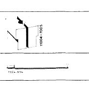 |
110 589 02 31 00
|
|||
|
Knocking-out mandrel 9 mm dia
|
110 589 02 15 00
|
||||
|
|
|||||
|
Removal
|
103-8363
|
||||
|
1 Remove radiator and fan.
|
|||||
|
2 Remove front crankshaft radial oil seal (03-324).
|
|||||
|
|
|||||
|
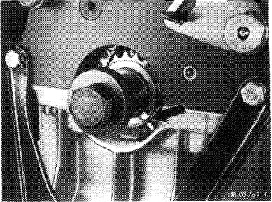
3 Use paint to mark both camshaft sprockets and camshaft sprocket to timing chain (arrow).
|
 |
||||
|
|
|||||
|
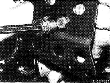
4 Remove chain tensioner (05—310).
|
 |
||||
|
|
|||||
|
03.2-350/2 F2
|
|||||
|
|
|||||
|
|
|||
|
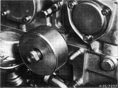
5 Remove guide rail in camshaft housing.
|
 |
||
|
|
|||
|
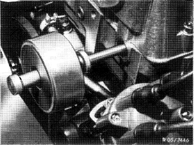
6 Remove reversing wheel. This requires unscrewing the plug and knocking out the bearing pin with an impact extractor (M 10 threaded pin).
7 Remove reversing wheel with a wire hook upward.
8 Remove oil pan to an extent that the timing chain can be taken off of the crankshaft sprocket.
|
 |
||
|
|
|||
|
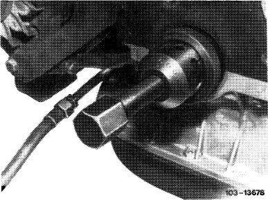
9 Pull-off spacing ring with puller.
|
 |
||
|
|
|||
|
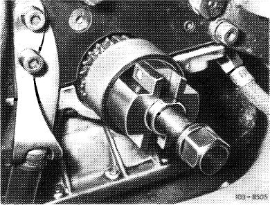
10 Pull off crankshaft sprocket with an extractor.
|
 |
||
|
|
|||
|
03.2-350/3 F2
|
|||
|
|
|||
|
|
|||
|
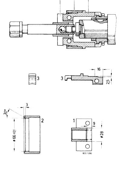
Note: Change puller 615 589 01 33 00 to dimensions shown in drawing.
|
 |
||
|
Installation
|
|||
|
11 Transfer color marks from old to new crankshaft gear.
|
|||
|
|
|||
|
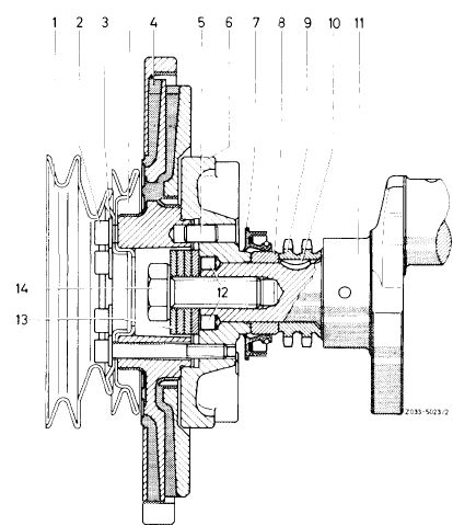
12 Heat crankshaft gear on a hot plate (approx. 80 °C) and slip on crankshaft.
13 Slip spacing ring on crankshaft.
|
 |
||
|
14 For further installation proceed vice versa, paying attention to pertinent color marks.
|
|||
|
|
|||
|
03.2-350/4 F2
|
|||
|
|
|||
