Removal and installation of flywheel and driven plate
|
|
|||||||||||||||||||||||||||||||||||||||||||||||||||||||||||||||||||||||||||||
|
03—410 Removal and installation of flywheel and driven plate
|
|||||||||||||||||||||||||||||||||||||||||||||||||||||||||||||||||||||||||||||
|
|
|||||||||||||||||||||||||||||||||||||||||||||||||||||||||||||||||||||||||||||
|
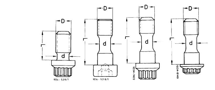
Necked down screws
|
for manual transmission
|
for automatic transmission
|
|||||||||||||||||||||||||||||||||||||||||||||||||||||||||||||||||||||||||||
|
|
|||||||||||||||||||||||||||||||||||||||||||||||||||||||||||||||||||||||||||||
 |
|||||||||||||||||||||||||||||||||||||||||||||||||||||||||||||||||||||||||||||
|
|
|||||||||||||||||||||||||||||||||||||||||||||||||||||||||||||||||||||||||||||
|
|||||||||||||||||||||||||||||||||||||||||||||||||||||||||||||||||||||||||||||
|
|
|||||||||||||||||||||||||||||||||||||||||||||||||||||||||||||||||||||||||||||
|
Initial torque
|
40 Nm
|
||||||||||||||||||||||||||||||||||||||||||||||||||||||||||||||||||||||||||||
|
|
|||||||||||||||||||||||||||||||||||||||||||||||||||||||||||||||||||||||||||||
|
Necked down screw for driven plate and flywheel
|
|||||||||||||||||||||||||||||||||||||||||||||||||||||||||||||||||||||||||||||
|
|
|||||||||||||||||||||||||||||||||||||||||||||||||||||||||||||||||||||||||||||
|
Torque angle
|
90-100°
|
||||||||||||||||||||||||||||||||||||||||||||||||||||||||||||||||||||||||||||
|
|
|||||||||||||||||||||||||||||||||||||||||||||||||||||||||||||||||||||||||||||
|
Special tool
|
|||||||||||||||||||||||||||||||||||||||||||||||||||||||||||||||||||||||||||||
|
|
|||||||||||||||||||||||||||||||||||||||||||||||||||||||||||||||||||||||||||||
|
Detent
|
 |
116 589 01 40 00
|
|||||||||||||||||||||||||||||||||||||||||||||||||||||||||||||||||||||||||||
|
|
|||||||||||||||||||||||||||||||||||||||||||||||||||||||||||||||||||||||||||||
|
03.2-410/1 F3
|
|||||||||||||||||||||||||||||||||||||||||||||||||||||||||||||||||||||||||||||
|
|
|||||||||||||||||||||||||||||||||||||||||||||||||||||||||||||||||||||||||||||
|
|
|||||||||||||||||||||||||||||||||||||||||||||||||||||||||||||||
|
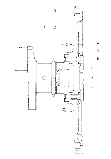
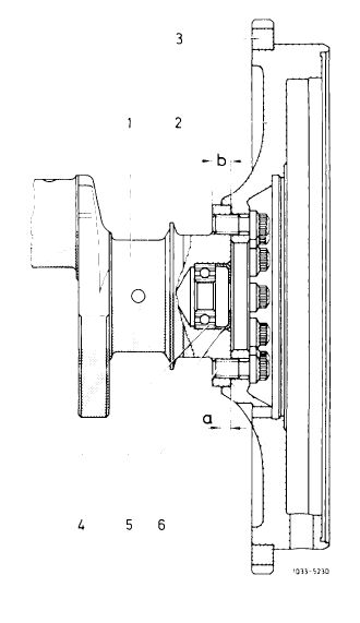
Note
Do not mix up flywheel for automatic transmission of 110 engine with flywheel for automatic transmission of 4-cylinder engines 115 and 615.
Engine 110 dimension a = 4.5 mm
Engine 115 and 615 dimension a = 6.5 mm
On exchange engines, the mounting bore in flywheel of 35 mm dia can be bored to 50.00—50.016 mm dia (50 H6) for transmission with hydraulic clutch (722.200/202).
|
 |
||||||||||||||||||||||||||||||||||||||||||||||||||||||||||||||
|
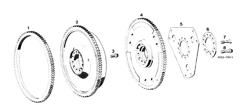
Layout of flywheel and driven plate for automatic transmission
|
|||||||||||||||||||||||||||||||||||||||||||||||||||||||||||||||
|
|||||||||||||||||||||||||||||||||||||||||||||||||||||||||||||||
|
|
|||||||||||||||||||||||||||||||||||||||||||||||||||||||||||||||
|
Layout flywheel for manual transmission
|
 |
||||||||||||||||||||||||||||||||||||||||||||||||||||||||||||||
|
1 Crankshaft
2 Flywheel
3 Ring gear
4 Ball bearing
|
5 Closing ring
6 Necked down screw a = 5 mm
b = 10 mm
|
||||||||||||||||||||||||||||||||||||||||||||||||||||||||||||||
|
|
|||||||||||||||||||||||||||||||||||||||||||||||||||||||||||||||
|
03.2-410/2 F3
|
|||||||||||||||||||||||||||||||||||||||||||||||||||||||||||||||
|
|
|||||||||||||||||||||||||||||||||||||||||||||||||||||||||||||||
|
|
||||
|
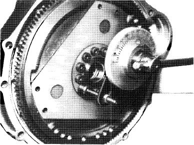
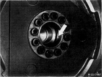
Removal
1 Loosen necked down screws, remove flywheel, driven plate and spacing washer.
Note: The flywheels and the crankshaft are marked together (arrow).
|
£03/7399′
|
|||
|
Flywheel manual transmission
|
||||
|
|
||||
|
Installation
|
 |
103-J0648
|
||
|
Note: If a new flywheel is installed, unbalance should be the same as for old flywheel (03—440).
|
||||
|
|
||||
|
2 Measure necked down dia d of necked down screws.
When the minimum dia is attained, replace necked down screws.
Necked down screws 1st and 2nd version for automatic transmission can be replaced by 3rd version.
|
||||
|
|
||||
|
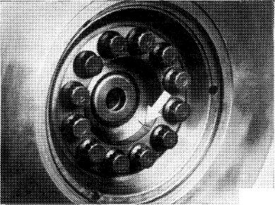
3 Position flywheel on crankshaft journal in such a manner that the markings (arrow) are in alignment.
|
 |
|||
|
Flywheel automatic transmission
|
||||
|
|
||||
|
03.2-410/3 F2
|
||||
|
|
||||
|
|
||||
|
4 Screw-in necked down screws and pre-tighten to 30—40 Nm with torque wrench.
|
||||
|
|
||||
|
5 Complete angle of rotation torque 90—100° by means of angle of rotation wrench.
|
103-8518
|
|||
|
|
||||
 |
||||
|
|
||||
|
1 Starter ring gear
2 Flywheel with starter ring gear for manual transmission
3 12 necked down screws
4 Flywheel with starter ring gear for automatic transmission
|
5 Driven plate
6 Spacing ring
7 12 necked down screws 1st version
8 12 necked down screws 2nd and 3rd version
|
|||
|
|
||||
|
03.2-410/4 F3
|
||||
|
|
||||