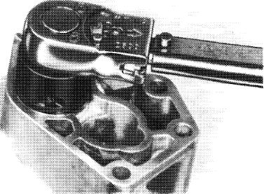
Removal and installation of thermostat in oil filter
|
|
||||||||||||||||||||||||||||||||||||
|
18—125 Removal and installation of thermostat in oil filter
|
||||||||||||||||||||||||||||||||||||
|
|
||||||||||||||||||||||||||||||||||||
|
||||||||||||||||||||||||||||||||||||
|
|
||||||||||||||||||||||||||||||||||||
|
Torque wrench 3/8″ square, 8-32 Nm
|
 |
001 589 51 21 00
|
||||||||||||||||||||||||||||||||||
|
|
||||||||||||||||||||||||||||||||||||
|
Socket 1/2″ square for valve seat ring
|
617 589 00 07 00
|
|||||||||||||||||||||||||||||||||||
|
|
||||||||||||||||||||||||||||||||||||
|
Note
|
||||||||||||||||||||||||||||||||||||
|
|
||||||||||||||||||||||||||||||||||||
|
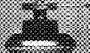
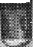
Remove functioning thermostat only at temperatures below 60 °C, since otherwise the thrust pin (a) will be pushed out.
Never pull thrust pin (a) out of wax thermostat (11), since otherwise proper function cannot be guaranteed.
|
 |
|||||||||||||||||||||||||||||||||||
|
|
 |
|
||||||||||||||||||||||||||||||||||
|
|
||||||||||||||||||||||||||||||||||||
|
|
||||||||||||||||||||||||||||||||||||
|
-11
|
||||||||||||||||||||||||||||||||||||
|
|
||||||||||||||||||||||||||||||||||||
|
Removal
|
 |
|||||||||||||||||||||||||||||||||||
|
1 Remove oil filter (18-110).
|
||||||||||||||||||||||||||||||||||||
|
2 Unscrew valve seat ring (17) by means of socket.
|
||||||||||||||||||||||||||||||||||||
|
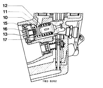
10 Compression spring
11 Thermostat
12 Control valve
13 Spring retainer
|
15 Compression spring
16 Return flow locking valve
17 Valve seat ring return flow locking valve
|
|||||||||||||||||||||||||||||||||||
|
|
||||||||||||||||||||||||||||||||||||
|
18.8-125/1 F2
|
||||||||||||||||||||||||||||||||||||
|
|
||||||||||||||||||||||||||||||||||||
|
|
|||
|
118-12434
|
|||
|
|
|||
|
3 Remove return flow locking valve (16) with compression spring (15), spring retainer (13), compression spring (10) and thermostat (11) with control valve (12).
|
|||
|
|
|||
|
Installation
|
|||
|
|
|||
|
5 Insert thermostat (11) with control valve (12), compression spring (10), spring retainer (13) and return flow locking valve (16) with compression spring (15).
6 Tighten valve seat ring (17) by means of socket to 35-45 Nm.
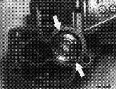
7 Peen valve seat ring in both recesses on oil filter housing (arrows) by means of a cross chisel.
8 Install oil filter with new gasket (18-110).
9 Run engine at idle and check for leaks.
10 Correct oil level.
|
 |
||
|
|
|||
|
18.8-125/2 F2
|
|||
|
|
|||
Poprzedni
