Removal and installation of front engine mount
|
|
|||
|
22—211 Removal and installation of front engine mount
|
|||
|
|
|||
|
Model 107
|
|||
|
|
|||
|
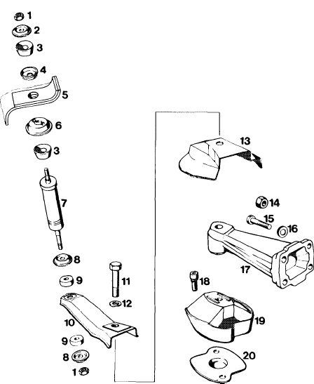
1 Unscrew screw (11).
2 Turn holder (10) and shielding plate (13) away in lateral direction.
3 Unscrew engine mount (19) from cross member.
4 Lift engine with pit lift at oil pan.
Note: Use wooden block to prevent damaging oil pan.
5 Remove engine mount together with shim (20).
6 For installation proceed vice versa.
7 Tighten screw (11) to 75 Nm.
Attention!
Check regulating linkage for function.
|
|||
|
|
|||
|
1 Nut
2 Cup spring 30 mm dia.
3 Rubber buffer 26 mm dia.
4 Cup spring 26 mm dia.
5 Holder
6 Cup spring 32 mm dia.
7 Engine shock absorber
8 Cup spring 26 mm dia.
9 Rubber buffer 22 mm dia.
10 Holder
11 Screw M 12 x 65
12 Spring washer
13 Shielding plate
14 Nut M 10 (7 each)
15 Screw M 10×65 (1 each)
16 Washer A 10.5 (6 each)
17 Engine carrier
18 Combination screw M 8 x 18
19 Engine mount
20 Shim
|
1004-7206
|
||
|
|
|||
|
22.2-211/1 F3
|
|||
|
|
|||
|
|
|||
|
Model 114
|
|||
|
|
|||
|
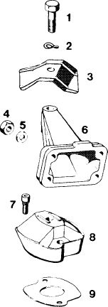
1 Unscrew screw (1).
2 Lift engine with pit lift at oil pan.
Note: Use wooden block to prevent damaging oil pan.
3 Unscrew screws from engine carrier and remove engine mount with shim.
4 For installation proceed vice versa.
5 Tighten screw (1) to 75 Nm.
|
|||
|
|
|||
|
1 Screw M 12 x 55
2 Spring washer B 12
3 Shielding plate (right)
4 Nut M 10
5 Washer A 10.5
6 Engine carrier
7 Combination screw M 8 x 18
8 Engine mount
9 Shim
|
 |
||
  |
|||
|
|
|||
|
22.2-211/2 F3
|
|||
|
|
|||
|
|
|||
|
Model 116
|
 |
||
|
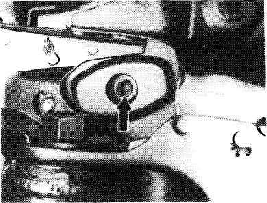
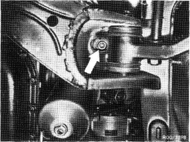
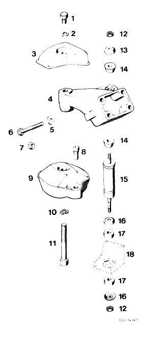
1 Unscrew screw (11, arrow) from underside of vehicle.
2 Unscrew nut (12) below on engine shock absorber.
3 Lift engine with pit lift at oil pan.
Note: Use wooden block to prevent damaging oil pan.
4 Unscrew screws (8) and remove engine mount (9).
5 For installation proceed vice versa.
6 Tighten screw (11) to 75 Nm.
|
|||
 |
|||
|
1 Screw
2 Spring washer
3 Shielding plate (right)
4 Engine carrier
5 Washer A 10.5 (6 each)
6 Screw M 10 x 65 (1 each)
7 Nut M 10 (7 each)
8 Combination screw M 8 x 18
9 Engine mount
10 Snap ring 12
11 Screw M 12×40
12 NutM6
13 Cup spring 30 mm dia.
14 Rubber buffer 26 mm dia.
15 Engine shock absorber
16 Cup spring 26 mm dia.
17 Rubber buffer 22 mm dia.
18 Holder
|
|||
|
|
|||
|
22.2-211/3 F3
|
|||
|
|
|||
|
|
|||
|
Model 123
|
100-11481
|
||
|
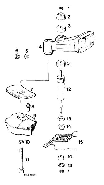
1 Unscrew screw (11, arrow) from underside of vehicle.
2 Unscrew nut below on engine shock absorber.
3 Lift engine with pit lift at oil pan.
Note: Use wooden block to prevent damaging oil pan.
4 Unscrew screws (8) and remove engine mount.
5 For installation proceed vice versa.
Note: Engine mounts left and right are different. The shielding plate is located at the right.
6 Tighten screw (11) to 75 Nm.
|
|||
 |
|||
|
1 NutM6
2 Cup spring 44 mm dia.
3 Rubber buffer 36 mm dia.
4 Engine carrier
5 Washer A 10.5 (6 each)
6 Nut M 10 (8 each)
7 Shielding plate
8 Combination screw M 8 x 18
9 Engine mount 123 241 10 13 (right) Engine mount 123 241 12 13 (left)
10 Snap ring 12
11 Screw M 12 x 35
12 Engine shock absorber
13 Cup spring 30 mm dia.
14 Rubber buffer 27 mm dia.
15 Holder
|
|||
|
|
|||
|
22.2-211/4 F3
|
|||
|
|
|||
|
|
|||
|
Model 126
|
 |
||
|
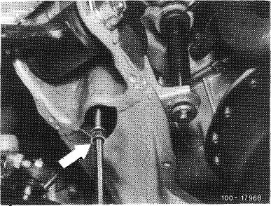
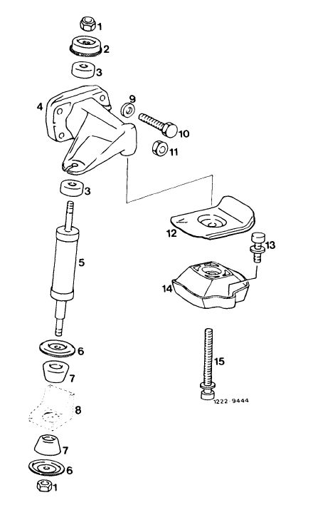
1 Unscrew screw (15, arrow) from underside of vehicle.
2 Unscrew nut (1) below on engine shock absorber.
3 Lift engine with pit lift at oil pan.
Note: Use wooden block to prevent damaging oil pan.
4 Unscrew screws (13) and remove engine mount.
5 For installation proceed vice versa.
Note: The shielding plate is located at the left.
6 Tighten screw (15, arrow) to 70 Nm.
|
|||
 |
|||
|
1 Nut M 6
2 Cup spring
3 Rubber buffer
4 Engine carrier
5 Engine shock absorber
6 Cup spring
7 Rubber buffer
8 Holder
9 Washer
10 Screw
11 Nut
12 Shielding plate
13 Combination screw
14 Engine mount
15 Screw
|
|||
|
|
|||
|
22.2-211/5 F3
|
|||
|
|
|||
