Checking fuel pump relay with electronic rpm regulation (breakaway)
|
|
||||||||||||||||||||||||||||
|
07.3—165 Checking fuel pump relay with electronic rpm regulation (breakaway)
|
||||||||||||||||||||||||||||
|
|
||||||||||||||||||||||||||||
|
Breakaway speeds
|
||||||||||||||||||||||||||||
|
|
||||||||||||||||||||||||||||
|
Engine
|
MB-part no.
|
Breakaway speed 1/min
|
Speed signal
|
|||||||||||||||||||||||||
|
|
||||||||||||||||||||||||||||
|
Without decel shutoff
|
||||||||||||||||||||||||||||
|
|
||||||||||||||||||||||||||||
|
Standard version and
|
starting model year 1981
|
|||||||||||||||||||||||||||
|
|
||||||||||||||||||||||||||||
|
110.984 110.986 110.987
|
001 545 07 05 001 545 14 05
|
6650 ± 50
|
||||||||||||||||||||||||||
|
|
||||||||||||||||||||||||||||
|
With decel shutoff
|
||||||||||||||||||||||||||||
|
|
||||||||||||||||||||||||||||
|
Standard version
|
||||||||||||||||||||||||||||
|
|
||||||||||||||||||||||||||||
|
||||||||||||||||||||||||||||
|
|
||||||||||||||||||||||||||||
|
Conventional testers
|
||||||||||||||||||||||||||||
|
|
||||||||||||||||||||||||||||
|
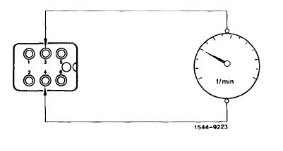
Voltmeter, revolution counter
|
||||||||||||||||||||||||||||
|
|
||||||||||||||||||||||||||||
|
07.3.2 lla-165/1 F2
|
||||||||||||||||||||||||||||
|
|
||||||||||||||||||||||||||||
|
|
||||
|
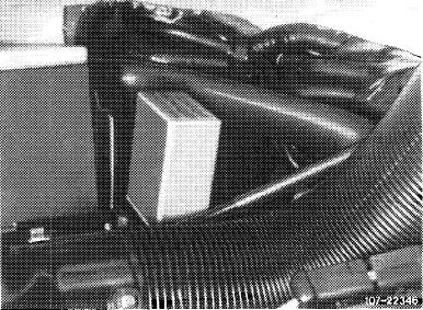
Layout fuel pump relay
|
 |
|||
|
Model 107
|
||||
|
Lefthand steering
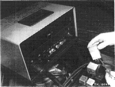
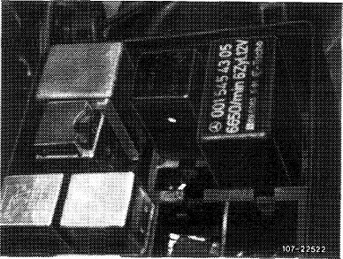
At the right inside vehicle behind glove box. For repairs, remove glove box.
|
||||
|
Righthand steering
|
Model 107
|
|||
|
|
||||
|
At the right inside vehicle above pedals.
|
||||
|
|
||||
|
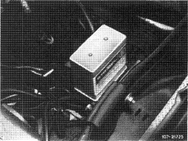
Model 123
|
 |
|||
|
Lefthand steering
|
||||
|
At the left on wheel house.
|
||||
|
Model 123
|
||||
|
|
||||
|
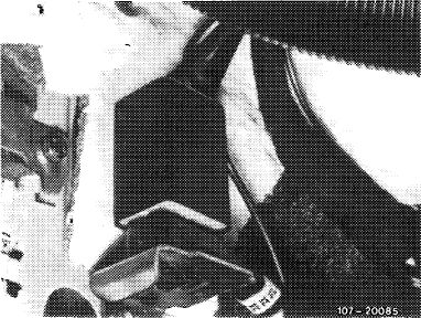
Righthand steering
At the left inside vehicle behind side panelling. Remove cover for repairs.
|
 |
|||
|
Model 123
|
||||
|
|
||||
|
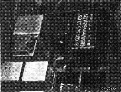
Model 126
|
 |
|||
|
Lefthand and righthand steering
|
||||
|
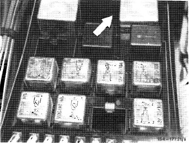
At the left in fuse box.
|
Model 126
|
|||
|
|
||||
|
07.3.2 Ma—165/2 F2
|
||||
|
|
||||
|
|
|||
|
A. Prior to September 1981
|
|||
|
|
|||
|
Testing
|
|||
|
|
|||
|
Test condition
|
|||
|
|
|||
|
Battery charged to min. 60 %.
|
|||
|
|
|||
|
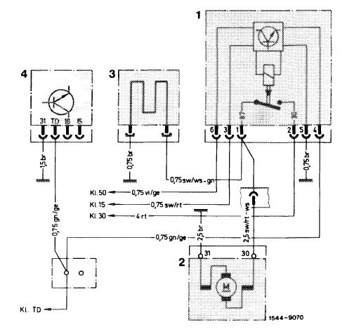
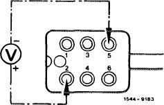
1 Fuel pump relay
2 Fuel pump
3 Warm-up compensator
4 TSZ (transistorized coil ignition) switching unit
|
 |
||
|
|
|||
|
07.3.2. Ma—165/3 F 2
|
|||
|
|
|||
|
|
|||
 |
 |
||
 |
|||
 |
|||
|
|
|||
|
07.3.2 I la—165/4 F2
|
|||
|
|
|||
|
|
||||
 |
 |
|||
 |
||||
|
|
||||
|
07.3.2 lla-165/5
|
F 2
|
|||
|
|
||||
|
|
|||
 |
 |
||
|
|
|||
|
07.3.2 lla-165/6 F2
|
|||
|
|
|||
|
|
||||
|
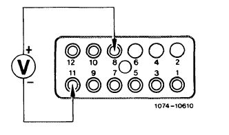
If engine is not regulated (breakaway) when attaining max. speed of engine, replace fuel pump relay.
The respective breakaway speed is punched into fuel pump relay.
|
||||
|
|
||||
|
End of test
|
||||
|
|
||||
|
B. Starting September 1981
|
||||
|
|
||||
 |
||||
|
|
||||
|
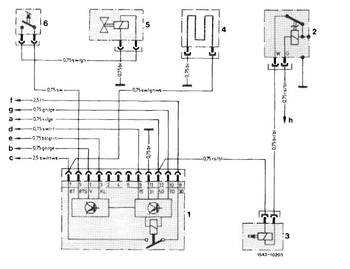
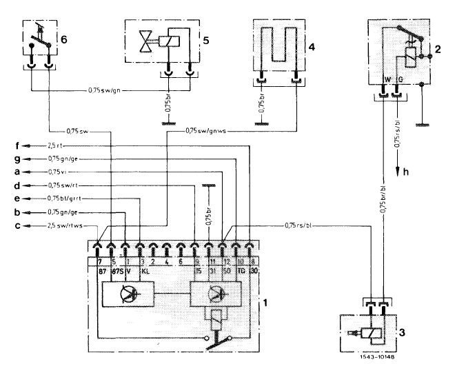
Wiring diagram model 123
1 Fuel pump relay
2 Thermo time switch
3 Cold starting valve
4 Warm-up compensator
5 Switchover valve
6 Microswitch
|
a To output starter lockout and backup lamp switch
b Transmitter mechanical tachometer
c Fuel pump
d Fuse 12 terminal 15 access
e Refrigerant compressor
f Cable connector engine terminal 30
g Cable connector terminal TD
h Cable connector engine terminal 50
|
Color code bl =blue br = brown ge = yellow gn = green gr =gray rs =pink rt = red sw = black vi = purple ws = white
|
||
|
|
||||
|
07.3.2 Ma—165/7 F2
|
||||
|
|
||||
|
|
||||
 |
||||
|
|
||||
|
Wiring diagram model 107,
1 Fuel pump relay
2 Thermo time switch
3 Cold starting valve
4 Warm-up regulator
5 Switchover valve
6 Microswitch
|
126
a Cable connector engine terminal 50
b Transmitter electronic tachometer
c Fuel pump
d Fuse 1 4 terminal 1 5 access
e Refrigerant compressor
f Cable connector terminal 30
g Cable connector terminal TD
h Cable connector terminal 50
|
Color code bl =blue br = brown ge = yellow gn = green gr =gray rs = pink rt = red sw = black vi = purple ws = white
|
||
|
|
||||
|
07.3.2 Ma—165/8 F2
|
||||
|
|
||||
|
|
|||
 |
 |
||
 |
|||
 |
|||
|
|
|||
|
07.3.2 lla-165/9 F2
|
|||
|
|
|||
|
|
|||
 |
 |
||
 |
|||
|
|
|||
|
07.3.2 Ma—165/10 F2
|
|||
|
|
|||
|
|
||||
 |
 |
|||
|
|
||||
|
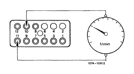
If engine is not regulated (breakaway) when engine max. speed is attained, replace fuel pump relay.
The respective breakaway speed is punched into fuel pump relay.
|
||||
|
|
||||
|
07.3.2 Ma —165/11
|
F 2
|
|||
|
|
||||