Checking fuel distributor for constant delivery
|
|
|||||||||||||||||||||||||||||||||||||||||||||||||||||||||||||||||||||||||||||||
|
07.3—160 Checking fuel distributor for constant delivery
|
|||||||||||||||||||||||||||||||||||||||||||||||||||||||||||||||||||||||||||||||
|
|
|||||||||||||||||||||||||||||||||||||||||||||||||||||||||||||||||||||||||||||||
|
Test values
|
|||||||||||||||||||||||||||||||||||||||||||||||||||||||||||||||||||||||||||||||
|
|
|||||||||||||||||||||||||||||||||||||||||||||||||||||||||||||||||||||||||||||||
|
|||||||||||||||||||||||||||||||||||||||||||||||||||||||||||||||||||||||||||||||
|
|
|||||||||||||||||||||||||||||||||||||||||||||||||||||||||||||||||||||||||||||||
|
) If the tester carriage is used for fuel distribution reference unit, an additional angle plate is required. The plate can be self-made or obtained from a Bosch representative.
Self made tool
|
|||||||||||||||||||||||||||||||||||||||||||||||||||||||||||||||||||||||||||||||
|
|
|||||||||||||||||||||||||||||||||||||||||||||||||||||||||||||||||||||||||||||||
|
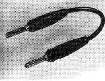
Contact bridge
|
 |
SC7-192O4
|
|||||||||||||||||||||||||||||||||||||||||||||||||||||||||||||||||||||||||||||
|
|
|||||||||||||||||||||||||||||||||||||||||||||||||||||||||||||||||||||||||||||||
|
07.3.2 I la—160/1 F2
|
|||||||||||||||||||||||||||||||||||||||||||||||||||||||||||||||||||||||||||||||
|
|
|||||||||||||||||||||||||||||||||||||||||||||||||||||||||||||||||||||||||||||||
|
|
|||
|
Note
|
 |
||
|
A fuel distribution reference unit is available for testing fuel distributor in vehicle. The unit serves to measure the individual amounts of fuel which the fuel distributor dispenses to the injection valves. Measurements are made with engine stopped. Operating conditions (idle, partial or full load) are simulated and set in air flow sensor plate by means of an adjusting device.
|
|||
|
|
|||
|
Testing
|
 |
||
|
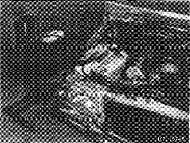
1 Set up fuel distribution reference unit horizontally adjacent to vehicle (tool or tester carriage).
2 Remove air cleaner.
3 Unscrew injection lines on fuel distributor and loosen at injection valves, unscrew, if required.
|
|||
|
|
|||
|
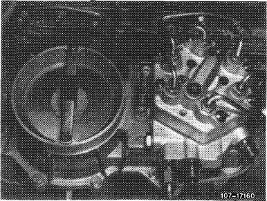
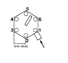
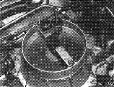
4 Connect connecting lines of fuel distribution reference unit to fuel distributor (sequence according to Fig.) and plug fuel return line into filler neck of fuel tank.
|
 |
||
|
|
|||
|
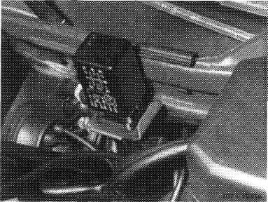
5 Clamp adjusting device for locating air flow sensor plate to stop bracket of air funnel (cone).
|
 |
||
|
|
|||
|
07.3.2 Ma —160/2 F 2
|
|||
|
|
|||
|
|
|||
|
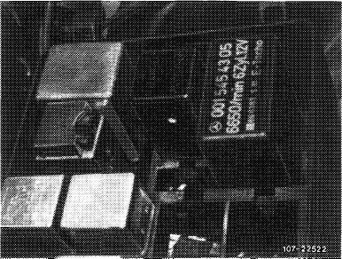
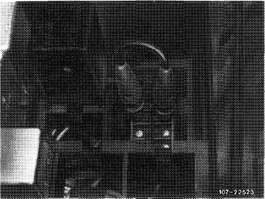
6 Switch-on ignition.
On vehicles without safety switch, pull off fuel pump relay and bridge the two jacks. This will connect the fuel pump to voltage.
Prior to September 1981: Jacks 1 and 2. Starting September 1981: Jacks 7 and 8.
|
 |
||
|
Model 123
|
|||
|
|
|||
|
Model 126
|
 |
||
|
|
|||
 |
|||
|
|
|||
|
7 Deflect air flow sensor plate and push buttons 1
to 6 for venting unit individually for a short moment.
8 Keep one button pushed, deflect air flow sensor plate with adjusting device and locate at a flow rate of 6 cc/min (idle).
9 Push remaining buttons, read individual flow rates and enter on data sheet.
|
|||
|
|
|||
|
07.3.2 I la-160/3 F2
|
|||
|
|
|||
|
|
||
|
Note: Orders for data sheets, print no. 800.99.472.00 should be mailed by service establishments and representatives in the Federal Republic of Germany with punch cards to the „Drucksachen-Zentrallager in Stutt-gart-Untertiirkheim” and by the general representatives in export countries to „ZKD/F 2″, Stuttgart-Untertiirk-heim. Data sheets are supplied in blocks of 50 sheets each.
10 Calculate difference between lowest and highest flow rate and compare with tolerance value (refer to test values).
11 For partial and full load, locate air flow sensor plate as described under item 7 at a flow rate of
30 cc/min or 100 cc/min. Then also calculate difference between lowest and highest flow rate and compare with tolerance value.
12 If the dispersion is outside tolerance, exchange fuel distributor.
13 Run engine and check all fuel connections for leaks.
14 Adjust idle speed (07.3-100).
|
||
|
|
||
|
07.3.2 I la 160/4 F2
|
||
|
|
||