Removal and installation of radiator
|
|
|||||||
|
20—420 Removal and installation of radiator
|
|||||||
|
|
|||||||
|
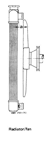
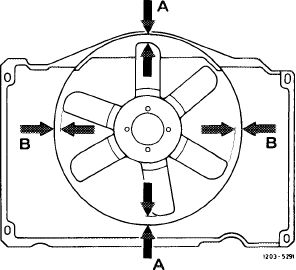
Installation dimensions for cooler — fan and fan — fan cover
|
|||||||
|
|
|||||||
|
Model
|
Fan distance „a”
for cooler approx. mm
|
Fan distance to fan cover approx. mm A
|
B
|
||||
|
|
|||||||
|
116.120
|
45
|
20
|
|||||
|
|
|||||||
|
123
|
25
|
||||||
|
|
|||||||
|
49
|
25
|
||||||
|
|
|||||||
|
126.120
|
|||||||
|
|
|||||||
 |
 |
||||||
|
Fan cover/fan
|
|||||||
|
|
|||||||
|
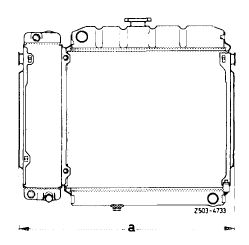
Installation dimensions for radiator with air-oil cooler
|
 |
||||||
|
Model
|
Installation dimension
|
||||||
|
„a” in mm
|
|||||||
|
116.120
|
685 ± 1
|
||||||
|
123
|
|||||||
|
673.5 ± 41)
|
|||||||
|
126.120
|
|||||||
|
l) Model 123.193 with air conditioning installation dimension „a” 681 ±4 mm.
|
|||||||
|
|
|||||||
|
20.8-420/1 F 2
|
|||||||
|
|
|||||||
|
|
|||||
|
Tightening torques
|
Nm
|
||||
|
|
|||||
|
Model 116
|
6-10
|
||||
|
|
|||||
|
Drain plug radiator
|
|||||
|
|
|||||
|
Models 123, 126
|
1.5-21)
|
||||
|
|
|||||
|
Lube oil hose to air-oil cooler
|
20-25
|
||||
|
|
|||||
|
Transmission fluid hose to transmission fluid cooler
|
15-20
|
||||
|
|
|||||
|
This torque can be obtained by means of a washer or a coin.
|
|||||
|
|
|||||
|
Special tools
|
|||||
|
|
|||||
|
Tester for cooling system
|
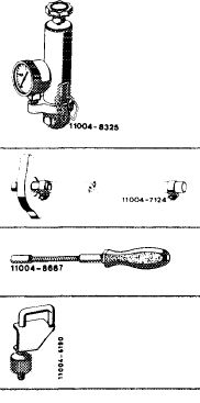 |
001 589 48 21 00
|
|||
|
Radiator cap with hose for leak tester
|
605 589 00 25 00
|
||||
|
7 mm socket on flexible shaft for hose clamps with worm drive
|
123 589 12 09 00
|
||||
|
Clamp
|
000 589 40 37 00
|
||||
|
|
|||||
|
Removal
|
|||||
|
|
|||||
|
1 Drain coolant from radiator (20—010), loosen coolant hoses on radiator and pull off.
2 Disconnect transmission fluid and lube oil hoses and unscrew on radiator or air-oil cooler.
The open connections of oil hoses and connections on radiators and coolers can be closed with plastic plugs.
|
|||||
|
|
|||||
|
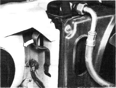
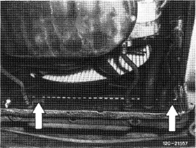
Model 116
3 Unscrew fan cover at top, pull out of holding clips at bottom and place over fan.
4 Push holder (arrow) in outward direction.
5 Lift out radiator together with air-oil cooler in upward direction.
|
 |
||||
|
Model 116
|
|||||
|
|
|||||
|
20.8-420/2 F 2
|
|||||
|
|
|||||
|
|
|||
|
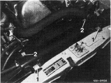
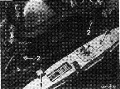
Models 123 and 126
6 Pull out both holding clamps (2) in upward direction.
|
 |
||
|
Model 123
|
|||
|
|
|||
|
Model 126
|
 |
||
|
|
|||
|
7 Lift fan cover out of lower holders (arrow) and place behind fan.
|
 |
||
|
Model 123
|
|||
|
|
|||
|
Model 126
|
 |
||
|
|
|||
|
20.8-420/3 F 2
|
|||
|
|
|||
|
|
|||
|
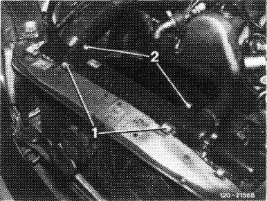
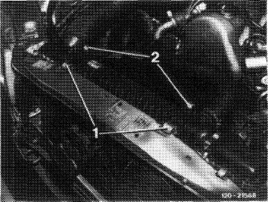
8 Pull out both holding clamps (1) in upward direction and lift out radiator together with air-oil cooler.
|
 |
||
|
Model 123
|
|||
|
|
|||
|
Model 126
|
 |
||
|
|
|||
|
Installation
|
 |
||
|
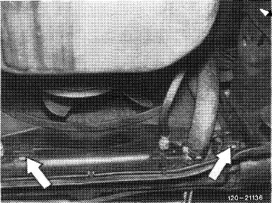
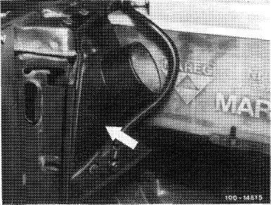
9 Insert radiator with air-coil cooler.
Note: On model 116, for positioning righthand holder (driving direction), unscrew intake scoop (arrow) and screw on again after fastening radiator.
10 For additional installation proceed vice versa to removal.
Pay attention to distance of fan in relation to radiator and to fan cover.
11 Pressure-test cooling system with tester (approx. 1 bar gage pressure).
|
|||
|
|
|||
|
20.8-420/4 F 2
|
|||
|
|
|||