Removal and installation of fuel tank
|
|
|||||||||||||||||||||||||||||||||||||||||||
|
47—700 Removal and installation of fuel tank
|
|||||||||||||||||||||||||||||||||||||||||||
|
|
|||||||||||||||||||||||||||||||||||||||||||
|
A. Model 116 ®1978-1980
|
|||||||||||||||||||||||||||||||||||||||||||
|
|
|||||||||||||||||||||||||||||||||||||||||||
|
|||||||||||||||||||||||||||||||||||||||||||
|
|
|||||||||||||||||||||||||||||||||||||||||||
|
Conventional tool
|
|||||||||||||||||||||||||||||||||||||||||||
|
|
|||||||||||||||||||||||||||||||||||||||||||
|
Torque wrench double arm, 1/2″ square, 15-65 Nm
|
e.g. Wille, D-5600 Wuppertal order no. 72 Nm/6
|
||||||||||||||||||||||||||||||||||||||||||
|
|
|||||||||||||||||||||||||||||||||||||||||||
|
Attention!
When removing fuel tank, pay attention to safety rules.
|
|||||||||||||||||||||||||||||||||||||||||||
|
|
|||||||||||||||||||||||||||||||||||||||||||
|
Removal
|
 |
||||||||||||||||||||||||||||||||||||||||||
|
1 Disconnect ground connection line on battery.
2 Drain fuel tank. Carefully pump off fuel, so that no residual fuel remains in fuel tank.
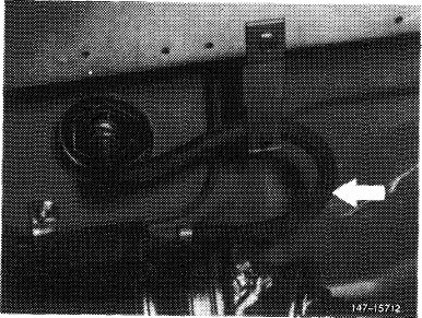
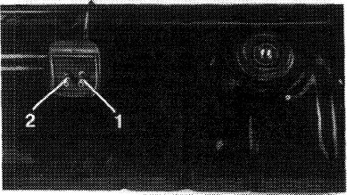
3 Loosen suction hose, return hose and vent hose (arrows). Collect residual fuell still in hoses. Close hoses and connections.
|
|||||||||||||||||||||||||||||||||||||||||||
|
|
|||||||||||||||||||||||||||||||||||||||||||
|
47.8-700/1 F 3
|
|||||||||||||||||||||||||||||||||||||||||||
|
|
|||||||||||||||||||||||||||||||||||||||||||
|
|
|||
 |
|||
|
|
|||
|
4 Remove trunk mat from trunk.
|
 |
||
|
5 Remove rear wall for fuel tank cover.
|
|||
|
|
|||
|
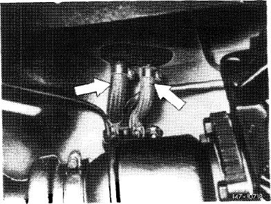
6 Unscrew fastening nuts (arrows).
7 Pull out fuel tank slightly and pull off coupler for fuel gauge.
8 Remove fuel tank.
|
 |
||
|
|
|||
|
Installation
|
|||
|
|
|||
|
9 Install fuel tank in vice versa sequence and proceed as follows:
a) Glue down both gaskets on underside of fuel tank by means of MB universal glue, part No. 000 989 92 71. For installation, coat both gaskets on sealing surface or bead with sliding compound (talcum, wax or the like).
|
 |
||
|
|
|||
|
1 Positive and negative vent line
2 Fuel return line
|
147-16744
|
||
|
|
|||
|
47.8-700/2 F 3
|
|||
|
|
|||
|
|
|||
|
b) Check whether foam rubber strips on fuel tank are tight, glue down with MB universal glue, part No. 000 989 92 71, if required.
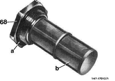
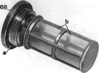
c) Blow out filter (b) and check for damage. Renew sealing ring (a). Tighten fuel filter (68) to 35-43 Nm.
d) Be sure to mount fuel tank with reinforcing plates and washers provided. Tighten fastening nuts to 17-25 Nm.
e) Pay attention to correct seat of rubber sleeve on fuel filler neck.
f) Plug-on coupler for fuel gage and check for function (ground connection line on battery connected).
g) Renew damaged fuel hoses, h) Check fuel system for leaks.
|
 |
||
|
|
|||
|
47.8-700/3 F 3
|
|||
|
|
|||
|
|
|||||||||||||||||||||||||||||||||||||||||||||||||||||||||||||||||||||||||||
|
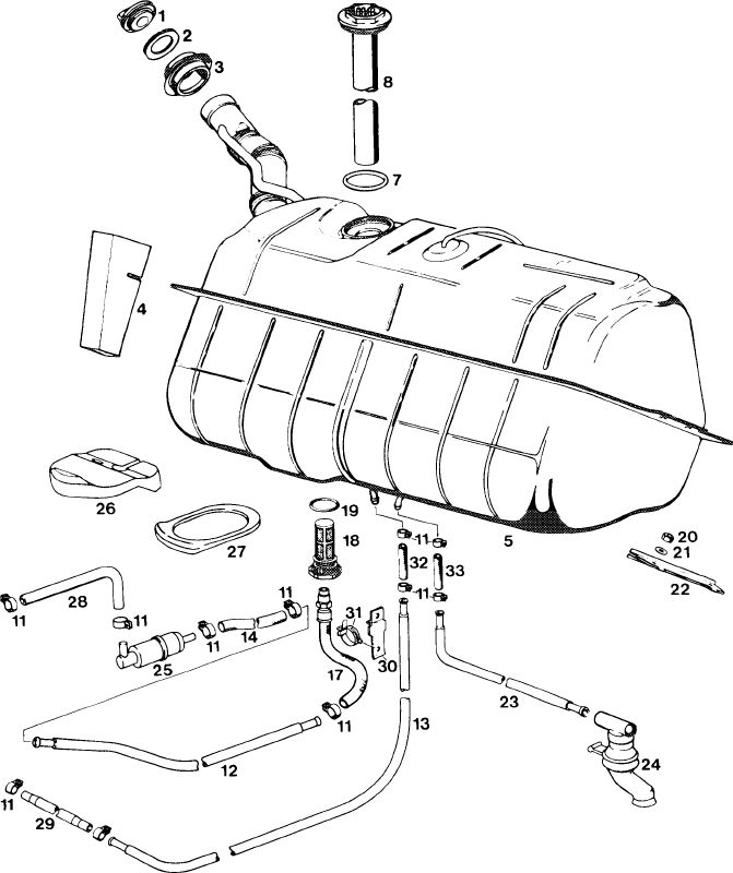
Fuel tank Model 116
|
|||||||||||||||||||||||||||||||||||||||||||||||||||||||||||||||||||||||||||
|
|
|||||||||||||||||||||||||||||||||||||||||||||||||||||||||||||||||||||||||||
|
1472-8380
11
|
|||||||||||||||||||||||||||||||||||||||||||||||||||||||||||||||||||||||||||
|
|
|||||||||||||||||||||||||||||||||||||||||||||||||||||||||||||||||||||||||||
|
1 Cap
2 Seal
3 Rubber sleeve
4 Damping insert
5 Fuel tank
7 Sealing ring
8 Immersion tube indicator (screw-type)
11 Hose clamp
12 Fuel feed line
13 Fuel return line
|
|
||||||||||||||||||||||||||||||||||||||||||||||||||||||||||||||||||||||||||
|
|
|||||||||||||||||||||||||||||||||||||||||||||||||||||||||||||||||||||||||||
|
47.8-700/4 F 3
|
|||||||||||||||||||||||||||||||||||||||||||||||||||||||||||||||||||||||||||
|
|
|||||||||||||||||||||||||||||||||||||||||||||||||||||||||||||||||||||||||||
|
|
|||||||||||||||||||||||||||||||
|
B. Model 123T-sedan
|
|||||||||||||||||||||||||||||||
|
|
|||||||||||||||||||||||||||||||
|
|||||||||||||||||||||||||||||||
|
|
|||||||||||||||||||||||||||||||
|
Fuel filter
|
|||||||||||||||||||||||||||||||
|
|
|||||||||||||||||||||||||||||||
|
35-43
|
|||||||||||||||||||||||||||||||
|
|
|||||||||||||||||||||||||||||||
|
Immersion tube indicator
|
|||||||||||||||||||||||||||||||
|
|
|||||||||||||||||||||||||||||||
|
Conventional tool
|
|||||||||||||||||||||||||||||||
|
|
|||||||||||||||||||||||||||||||
|
Torque wrench double arm, 1/2″ square, 15-65 Nm
|
e.g. Wille, D-5600 Wuppertal order no. 72 Nm/6
|
||||||||||||||||||||||||||||||
|
|
|||||||||||||||||||||||||||||||
|
Attention!
When removing fuel tank, pay attention to safety rules.
|
|||||||||||||||||||||||||||||||
|
|
|||||||||||||||||||||||||||||||
|
Removal
|
 |
||||||||||||||||||||||||||||||
|
1 Disconnect ground connecting line on battery.
2 Drain fuel tank. Carefully pump off fuel, so that no residual fuel remains in fuel tank.
3 Remove trunk floor and intermediate shelf.
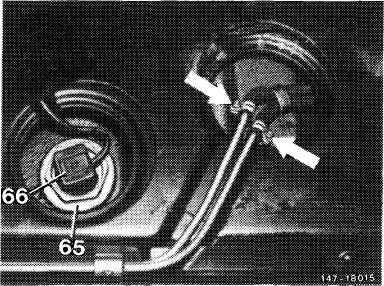
4 Pull off coupler (66) for fuel gage.
5 Loosen hose clips (arrows) on vent lines, pull off hoses, tightly close lines and hoses.
47.8-700/5 F 3
|
|||||||||||||||||||||||||||||||
|
|
|||||||||||||||||||||||||||||||
|
|
|||
|
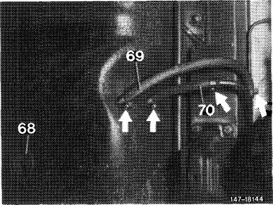
6 Loosen hose clamps on front (69) and return line (70), pull off both hoses on fuel tank and catch residual fuel in hose (69). Tightly close hoses and filler neck.
|
 |
||
|
|
|||
|
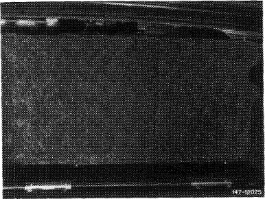
7 Loosen hose clamp (arrow) and pull off vent hose. Close hose and filler neck.
8 Unscrew fastening nuts and remove fuel tank in downward direction.
|
 |
||
|
|
|||
|
Installation
|
 |
||
|
9 Install fuel tank in vice versa sequence and proceed as follows:
a) Glue foam rubber strip on fuel tank at level of filler neck crosswise to driving direction.
Note: Never use felt or similar material, since otherwise corrosion damage may result.
b) Blow out filter (b) and check for damage. Renew sealing ring (a). Install fuel filter (68) and tighten
to 35-43 Nm,
c) Be sure to install fuel tank with specified reinforcing plates and washers. Tighten self-locking fastening nuts to 26-34 Nm.
d) Install vent hose (arrow) between fuel tank and filler neck free of kinks and with a continuous slope toward fuel tank.
The slipped-on O-ring serves for sealing at passage to interior.
|
|||
 |
|||
|
|
|||
|
47.8-700/6 F 3
|
|||
|
|
|||
|
|
|||
|
e) Pay attention to correct seat of sleeves on filler neck.
f) Renew damaged fuel hoses.
g) Check operation of fuel gage (ground connection line on battery connected).
h) Check fuel system for leaks.
|
|||
|
|
|||
|
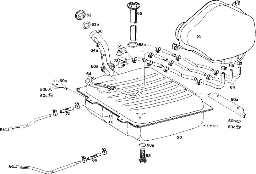
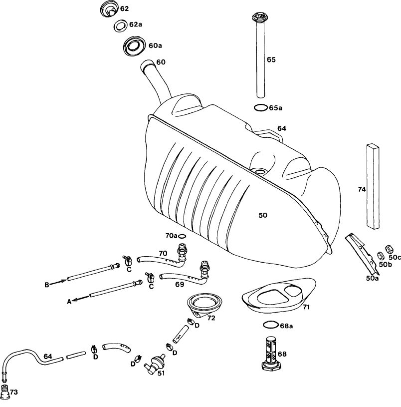
Fuel tank
Model 123T-sedan
|
|||
|
|
|||
 |
|||
|
|
|||
|
50 Fuel tank
50a Reinforcing plate
50b Washer
50c Self-locking nut
51 Vent valve ((uSA)only starting 1981! 55 Expansion tank
60 Filter neck
60a Sealing sleeve (2 each)
62 Cap
62a Sealing ring
|
64 Vent line
64a Negative vent line
65 Immersion tube indicator 65a Sealing ring
68 Fuel filter 68a Sealing ring
69 Feed line
70 Return line 73 Vent sleeve
|
||
|
|
|||
|
47.8-700/7 F 3
|
|||
|
|
|||
|
|
|||||||||||||||||||||||||||||||||||||||||||
|
C. Model 126 ® starting 1981
|
|||||||||||||||||||||||||||||||||||||||||||
|
|
|||||||||||||||||||||||||||||||||||||||||||
|
|||||||||||||||||||||||||||||||||||||||||||
|
|
|||||||||||||||||||||||||||||||||||||||||||
|
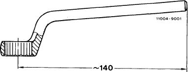
Self-made tool (model 126)
|
|||||||||||||||||||||||||||||||||||||||||||
|
|
|||||||||||||||||||||||||||||||||||||||||||
|
Conventional, offset box end wrench 19 mm, shorten according to drawing
|
 |
||||||||||||||||||||||||||||||||||||||||||
|
|
|||||||||||||||||||||||||||||||||||||||||||
|
Attention!
When removing fuel tank, pay attention to safety rules.
|
|||||||||||||||||||||||||||||||||||||||||||
|
|
|||||||||||||||||||||||||||||||||||||||||||
|
47.8-700/8 F 3
|
|||||||||||||||||||||||||||||||||||||||||||
|
|
|||||||||||||||||||||||||||||||||||||||||||
|
|
|||
|
Removal
|
 |
||
|
1 Disconnect ground connection line on battery.
2 Drain fuel tank. Carefully pump off fuel so that no residual fuel remains in fuel tank.
3 Remove trunk mat.
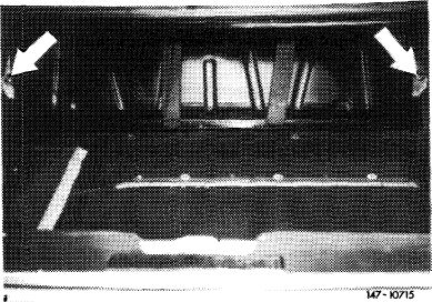
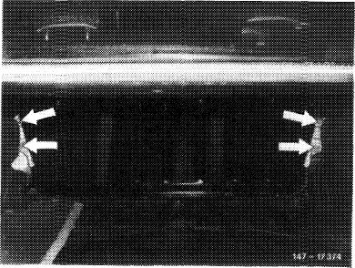
4 Remove rear wall for fuel tank cover. For this purpose, unscrew fastening screws (arrows).
|
|||
|
|
|||
|
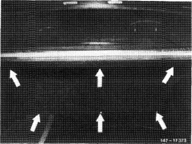
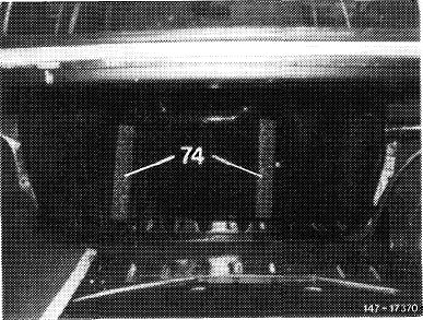
5 Unscrew fuel tank fastening nuts (arrows).
|
 |
||
|
|
|||
|
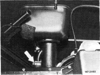
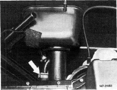
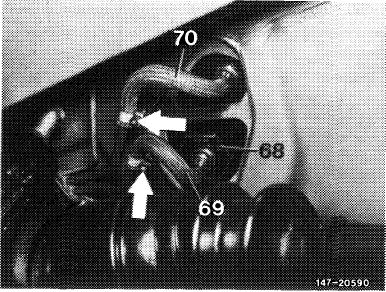
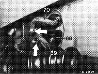
6 Remove suction hose (69) and return flow hose (70) (use shortened box end wrench for return flow hose).
Note: Carefully catch residual fuel from lines. Tightly close lines and fuel tank.
|
 |
||
|
|
|||
|
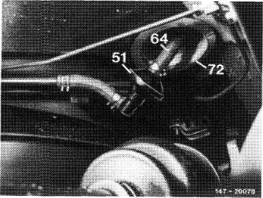
7 Pull hose (64) from vent line and tightly close hose and line.
|
 |
||
|
51 Vent valve
(USA) only starting 1981
|
|||
|
|
|||
|
47.8-700/9 F 3
|
|||
|
|
|||
|
|
|||
|
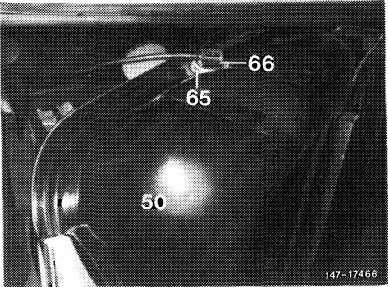
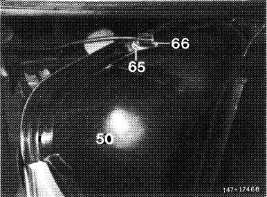
8 Lift fuel tank (50) out of mounting bracket and pull to the rear until coupler (66) for fuel gage can be pulled from immersion tube indicator (65).
9 Remove fuel tank.
|
 |
||
|
|
|||
|
Installation
|
|||
|
|
|||
|
10 Install fuel tank in vice versa sequence while proceeding as follows:
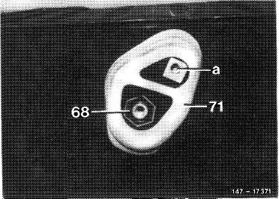
a) Check gasket (71) for tight seat and glue down with MB universal glue, part No. 000 989 92 71, if required. For installation, coat sealing bead with sliding compound (talcum, wax or the like).
|
 |
||
|
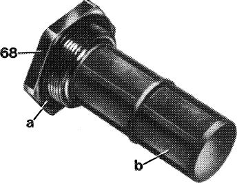
68 Connection intake hose
71 Gasket
a Connection return flow line
|
|||
|
|
|||
|
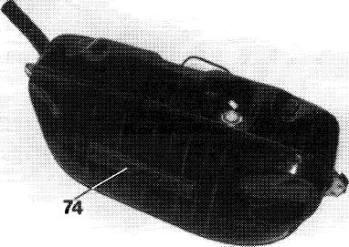
b) Check damping shims (74) for tight seat and glue down with MB universal glue, part No. 000 989 92 71, if required.
|
 |
||
|
|
|||
 |
|||
|
147-174&3
|
|||
|
|
|||
|
47.8-700/10 F2
|
|||
|
|
|||
|
|
|||
|
c) Blow out filter (b) and check for damage. Renew sealing ring (a). Tighten fuel filter (68) to 35—43 Nm).
|
 |
||
|
|
|||
 |
|||
|
|
|||
|
d) When installing fuel tank, make sure that coupler (66) is plugged on immersion tube indicator (65). Check for function.
e) Mount fuel tank with reinforcing plates and washers provided. Tighten fastening nuts to 17—25 Nm.
f) Pay attention to correct seat of sealing sleeve on filler neck, of gaskets between fuel tank and trunk floor and of sealing sleeve on vent line.
g) Replace copper sealing ring between fuel tank and return flow hose (70).
h) Renew damaged fuel hoses. i) Check fuel system for leaks.
|
 |
||
|
|
|||
 |
|||
|
|
|||
|
47.8-700/11 F3
|
|||
|
|
|||
|
|
|||||||||||||||||||||||||||||||||||||||||||||||||||||||||||||||||||||||||||||||||||||||
|
Fuel tank Model 126
|
|||||||||||||||||||||||||||||||||||||||||||||||||||||||||||||||||||||||||||||||||||||||
|
|
|||||||||||||||||||||||||||||||||||||||||||||||||||||||||||||||||||||||||||||||||||||||
 |
|
||||||||||||||||||||||||||||||||||||||||||||||||||||||||||||||||||||||||||||||||||||||
|
|
|||||||||||||||||||||||||||||||||||||||||||||||||||||||||||||||||||||||||||||||||||||||
|
|||||||||||||||||||||||||||||||||||||||||||||||||||||||||||||||||||||||||||||||||||||||
|
|
|||||||||||||||||||||||||||||||||||||||||||||||||||||||||||||||||||||||||||||||||||||||
|
47.8-700/12 F3
|
|||||||||||||||||||||||||||||||||||||||||||||||||||||||||||||||||||||||||||||||||||||||
|
|
|||||||||||||||||||||||||||||||||||||||||||||||||||||||||||||||||||||||||||||||||||||||