Removal and installation of exhaust gas turbocharger
|
|
||||
|
09—430 Removal and installation of exhaust gas turbocharger
|
||||
|
|
||||
|
Turbocharger designation
|
||||
|
|
||||
|
Garret
|
TA 0301
|
|||
|
|
||||
|
Kiihnle Kopp and Kausch KKK 532 679 60 31;
|
||||
|
|
||||
|
x) Start of production
World-wide except<@): January 1983 (us£): February 1983
|
 |
|||
|
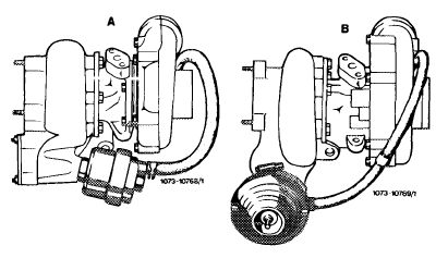
A Garret turbocharger B KKK turbocharger
|
||||
|
|
||||
|
Removal
|
 |
|||
|
1 Remove air filter, detaching air filter cover and unscrewing 3 fastening nuts.
|
||||
|
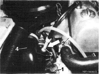
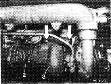
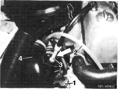
2 On vehicles with automatic climate control or air-conditioning remove electric line for
100° C temperature switch (1).
3 Release lower hose clip (arrow) on intake line (4) from air filter to compressor housing. On vehicles up to model 1979 only.
4 Remove vacuum line (2) and crankcase ventilation pipe (3).
5 Remove air filter with intake line (4).
|
||||
 |
||||
|
1 Temperature switch 100 C
2 Vacuum line
3 Crankcase ventilation pipe
4 Intake line
|
||||
|
|
||||
|
09.8-430/1 F 3
|
||||
|
|
||||
|
|
|||
|
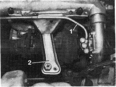
6 Unscrew engine oil supply line (1).
7 Unscrew air filter holder (2). To do so, release 3 hex-head bolts (2 from above, 1 from below) and remove holder.
|
 |
||
|
1 Engine oil supply line
2 Air filter holder
|
|||
|
|
|||
|
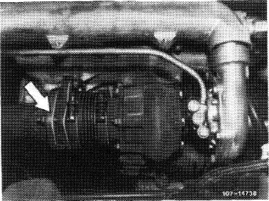
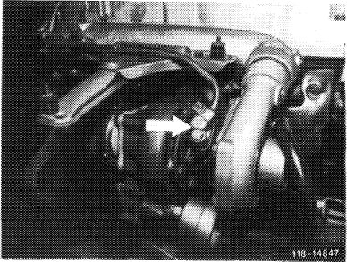
8 Unscrew exhaust flange (arrow).
9 Release and remove exhaust holder on automatic transmission.
10 Force exhaust pipe toward rear.
|
 |
||
|
|
|||
|
11 Unscrew holder (1) for adapter fitting (2).
12 Unscrew 4 fastening nuts (arrows) at exhaust-driven turbocharger and remove turbocharger.
13 Unscrew adapter fitting (2) at exhaust-driven turbocharger (3).
|
 |
||
|
1 Holder
2 Adapter fitting
3 Turbocharger
|
|||
|
|
|||
|
09.8-430/2 F 3
|
|||
|
|
|||
|
|
|||
|
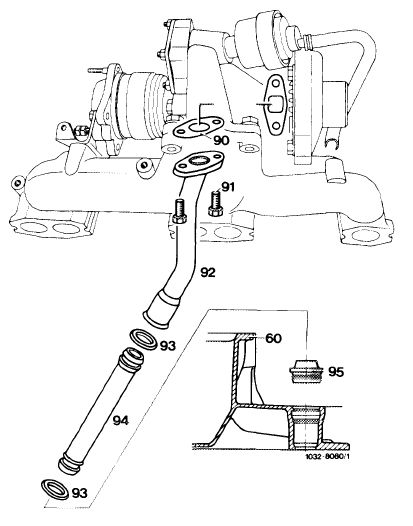
14 Unscrew oil return pipe (92) at turbocharger.
|
 |
||
|
60 Oil pan, upper part
90 Gasket
91 2 bolts M 8 x 20
92 Oil return pipe (upper part)
93 O-ring
94 Oil return pipe (lower part)
95 Sectional seal
|
|||
|
|
|||
|
Installation
|
|||
|
|
|||
|
Install in reverse order, using new gaskets (repair set). Please note the following points:
15 Prior to installing turbocharger, attach adapter fitting and oil return pipe. Correct positioning is absolutely essential.
|
|||
|
|
|||
|
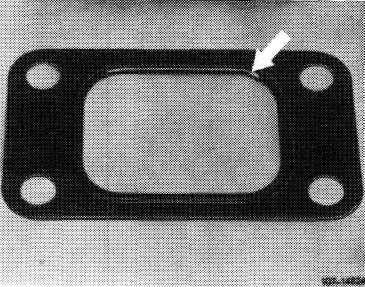
16 Insert flange gasket between turbocharger and exhaust manifold so that bead (arrow) is at exhaust manifold side.
17 Always use heat-resistant nuts and bolts to
attach the turbocharger.
|
 |
||
|
|
|||
|
09.8-430/3 F 3
|
|||
|
|
|||
|
|
|||
|
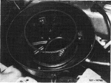
18 Prior to using a replacement turbocharger, fill with approx. 1/8 I engine oil through engine oil supply hole (arrow).
|
 |
||
|
|
|||
|
19 Make sure that intake line (4) is fitted in such a way that rubber sealing rings are correctly positioned.
|
 |
||
|
1 Temperature switch
2 Vacuum line
3 Ventilation pipe
4 Intake line
|
|||
|
|
|||
|
09.8-430/4 F 3
|
|||
|
|
|||
|
|
||||
|
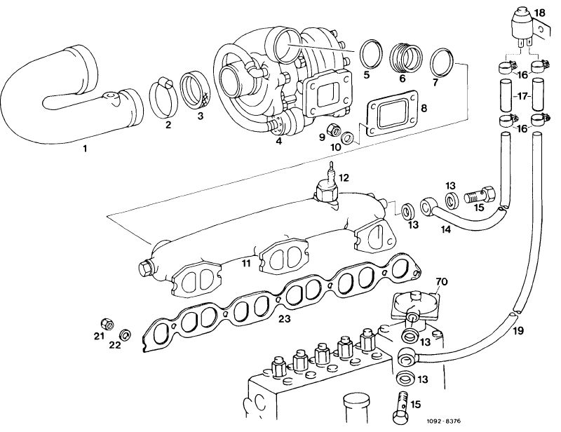
A. Exhaust Gas Turbocharger
|
||||
|
|
||||
 |
||||
|
|
||||
|
1 Intake line
2 Hose clip
3 Rubber sealing ring
4 Turbocharger
5 Rubber sealing ring
6 Adapter fitting
7 Rubber sealing ring
8 Flange gasket
|
9 Heat-resistant nut 1 7
10 Washer 18
11 Intake manifold 19
12 Pressure switch 21
13 Sealing ring 22
14 Delivery line from intake manifold 23
15 Union screw 70
16 Hose clip
|
Connecting hose
Switchover valve
Delivery line to aneroid compensator
Nut
Washer
Gasket
Aneroid compensator
|
||
|
|
||||
|
09.8-430/5 F 3
|
||||
|
|
||||