Adjusting throttle linkage
|
|
||||||||||||||||||||||||||||||||
|
30-300 Adjusting throttle linkage
|
||||||||||||||||||||||||||||||||
|
|
||||||||||||||||||||||||||||||||
|
A. Model 123.193 standard version
|
||||||||||||||||||||||||||||||||
|
|
||||||||||||||||||||||||||||||||
|
1st version
|
||||||||||||||||||||||||||||||||
|
|
||||||||||||||||||||||||||||||||
|
||||||||||||||||||||||||||||||||
|
|
||||||||||||||||||||||||||||||||
 |
||||||||||||||||||||||||||||||||
|
|
||||||||||||||||||||||||||||||||
|
Connecting rod (5 in Fig. item 4)
|
118
|
|||||||||||||||||||||||||||||||
|
|
||||||||||||||||||||||||||||||||
|
Auxiliary tool (spare part)
|
||||||||||||||||||||||||||||||||
|
|
||||||||||||||||||||||||||||||||
|
Adjusting sleeve (5 in Fig. item 5)
|
 |
180 072 03 93
|
||||||||||||||||||||||||||||||
|
|
||||||||||||||||||||||||||||||||
|
30.8-300/1 F 3
|
||||||||||||||||||||||||||||||||
|
|
||||||||||||||||||||||||||||||||
|
|
||||||||||||||||||||||||||||||||||||||||||||||||||||||||
|
Adjustment
1 Check throttle linkage for easy operation and bends. Replace damaged parts, if any.
2 Disconnect all regulating rods.
|
||||||||||||||||||||||||||||||||||||||||||||||||||||||||
|
|
||||||||||||||||||||||||||||||||||||||||||||||||||||||||
|
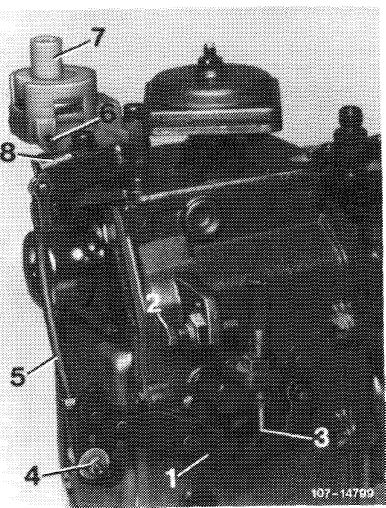
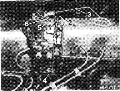
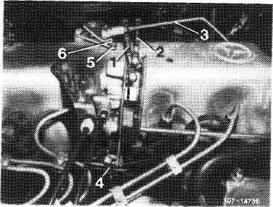
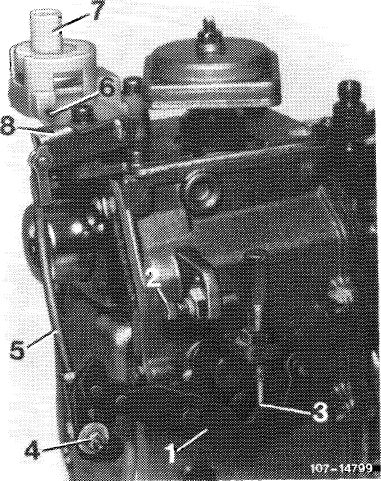
3 Check whether regulating lever (1) of injection pump rests against idle speed stop (3).
4 Check whether connecting rod (5) is correctly set. For this purpose, push regulating lever (1) against full load stop (2). Actuating lever (8) should have a max. play of 0.5 mm up to full load stop (6). If required, adjust connecting rod (5) by means of adjustable ball head (4).
Connecting rod (5) should be set to 122 mm, measured from center of ball socket to center of linkage.
|
 |
|||||||||||||||||||||||||||||||||||||||||||||||||||||||
|
1 Regulating lever
2 Full load stop
3 Idle speed stop
4 Adjustable ball head
5 Connecting rod
6 Full load stop on vacuum control valve
7 Vacuum control valve
8 Actuating lever for vacuum control valve
|
||||||||||||||||||||||||||||||||||||||||||||||||||||||||
|
|
||||||||||||||||||||||||||||||||||||||||||||||||||||||||
|
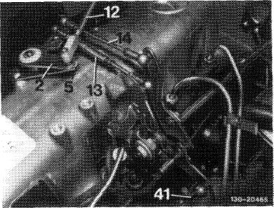
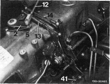
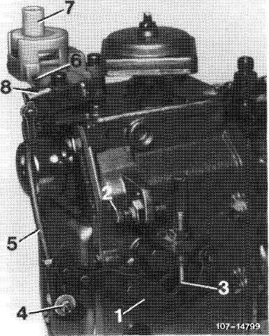
5 Plug-on adjusting sleeve (5). Guide lever should rest against sleeve.
6 Set free travel rod (13) in completely pulled out condition to 154 mm, measured from center to center of ball head and connect.
|
 |
|||||||||||||||||||||||||||||||||||||||||||||||||||||||
|
||||||||||||||||||||||||||||||||||||||||||||||||||||||||
|
|
||||||||||||||||||||||||||||||||||||||||||||||||||||||||
|
|
|||
|
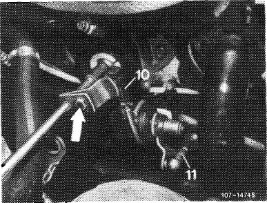
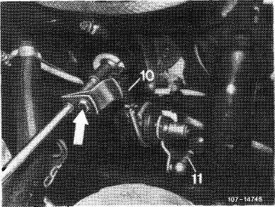
7 Push guide lever (2) against idle speed stop.
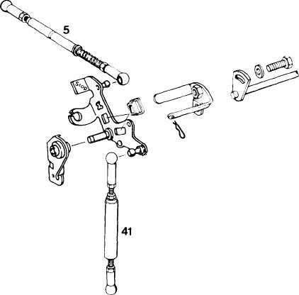
8 Adjust pushrod (41) in such a manner that rod can be connected free of tension.
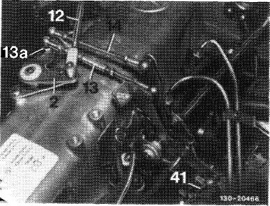
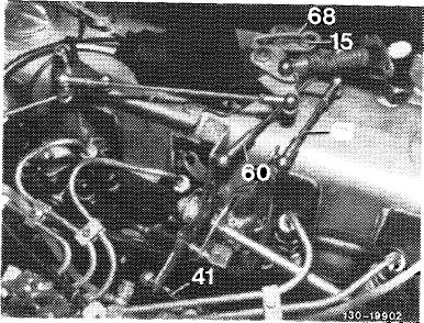
9 Set connecting rod (14) to 140 mm, measured from center to center of ball head and connect.
10 Set regulating lever on injection pump to full load.
|
|||
|
|
|||
|
Adjust adjustable ball head (13a) in slot, if required.
|
 |
||
|
|
|||
|
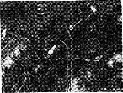
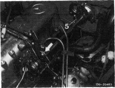
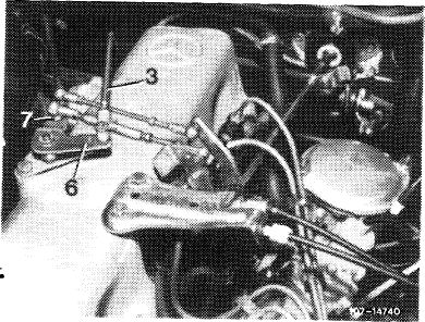
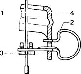
11 Adjust control pressure rod (12). Guide lever (2) should rest against idle speed stop. Push control pressure rod carefully against idle speed stop on transmission, set to tension-free length, connect and secure.
Note: To facilitate assembly, make sure that trademark faces in upward direction when end piece is connected.
During longitudinal checkup, hold control pressure rod above test bore adjacent to bolt.
|
|||
|
|
|||
|
12 Remove adjusting sleeve (5).
|
 |
||
|
|
|||
|
30.8-300/3 F2
|
|||
|
|
|||
|
|
|||
|
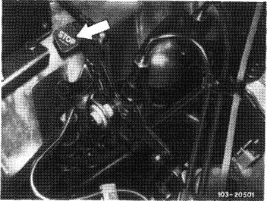
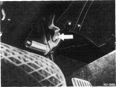
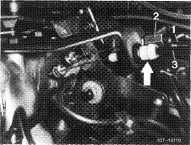
13 Check full load stop. With engine stopped, push accelerator pedal from inside vehicle up to stop on kickdown switch. Accelerator pedal and regulating lever on injection pump should rest against full load stop. If required, loosen adjusting screw (arrow). Adjust throttle linkage in such a manner that the regulating lever rests against full load stop.
|
 |
||
|
|
|||
|
If this adjustment is not enough to attain full load or !-Jle speed stop, set pushrod (5) from longitudinal regulating shaft to accelerator pedal to 200 mm, measured from center of ball socket to center of damping ring.
|
 |
||
|
|
|||
|
30.8-300/4 F2
|
|||
|
|
|||
|
|
||||
|
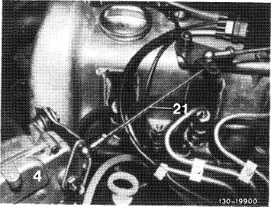
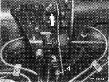
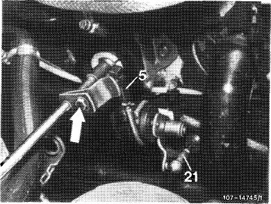
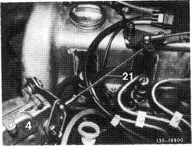
14 Adjust cruise control. Check whether actuator rests against idle speed stop of cruise control. For this purpose, disconnect connecting rod (21) and push lever of actuator (4) clockwise against idle speed stop. When attaching connecting rod (21), make sure that the lever of the actuator is pushed away from idle speed stop by approx. 1 mm. Adjust connecting rod, if required.
|
 |
|||
|
|
||||
|
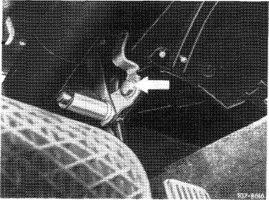
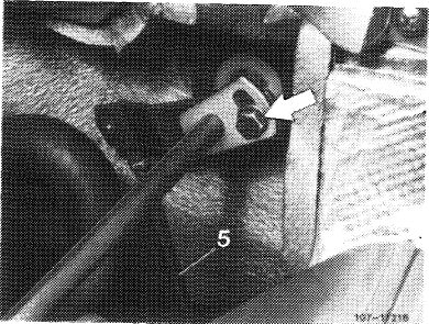
15 Check operation of emergency stop button. For this purpose, run engine at idle, push emergency stop button (arrow). Engine should stop, readjust pushrod toward injection pump, if required.
|
 |
|||
|
|
||||
|
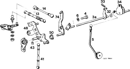
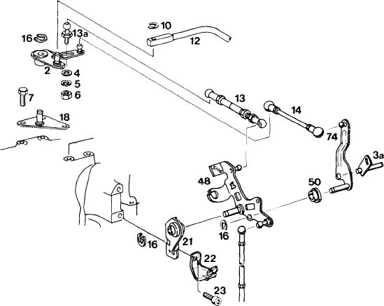
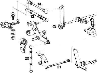
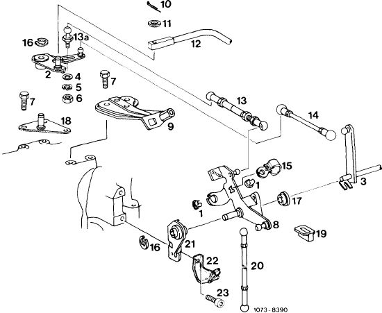
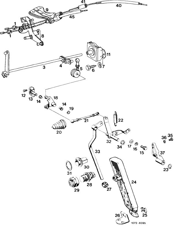
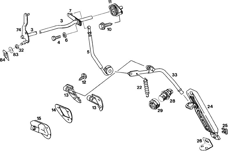
Engine regulation
|
||||
|
|
||||
|
2 Guide lever
3a Longitudinal regulating shaft
4 Washer
5 Corrugated washer
6 Nut
7 Screw 10 Lock
12 Control pressure rod
13 Free travel rod
13a Screw-type ball head
14 Connecting rod 16 Lock
18 Holder
21 Holder
22 Holder
23 Hex. socket screw 41 Pushrod
48 Angle lever
50 Plastic bushing
74 Guide lever
|
 |
|||
|
O 1073-8390 1
|
||||
|
|
||||
|
30.8-300/5 F2
|
||||
|
|
||||
|
|
|||||||||||||||||||||||||||||||||||||||||||||||||||||||||||||||||||||
|
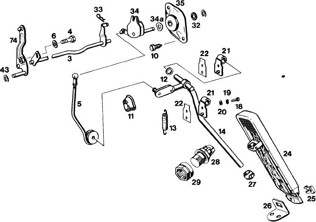
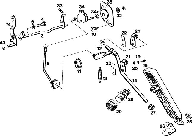
Chassis regulation
|
|||||||||||||||||||||||||||||||||||||||||||||||||||||||||||||||||||||
|
|
|||||||||||||||||||||||||||||||||||||||||||||||||||||||||||||||||||||
|
43
|
|||||||||||||||||||||||||||||||||||||||||||||||||||||||||||||||||||||
|
1303-9960C
|
|||||||||||||||||||||||||||||||||||||||||||||||||||||||||||||||||||||
|
|
|||||||||||||||||||||||||||||||||||||||||||||||||||||||||||||||||||||
|
27 Joint
28 Kickdown switch
29 Adjusting nut
32 Copper netting-graphite disk
33 Lock
34 Regulating lever with damper 34a Corrugated washer
35 Bearing bracket 43 Lock
|
||||||||||||||||||||||||||||||||||||||||||||||||||||||||||||||||||||
|
|
|||||||||||||||||||||||||||||||||||||||||||||||||||||||||||||||||||||
|
30.8-300/6 F 3
|
|||||||||||||||||||||||||||||||||||||||||||||||||||||||||||||||||||||
|
|
|||||||||||||||||||||||||||||||||||||||||||||||||||||||||||||||||||||
|
|
|||||||||||||||||||||||||||||
|
2nd version
|
|||||||||||||||||||||||||||||
|
|
|||||||||||||||||||||||||||||
|
Length of regulating rods in mm
|
|||||||||||||||||||||||||||||
|
|
|||||||||||||||||||||||||||||
|
Idle travel rod with elastic stop (5)
|
184
|
||||||||||||||||||||||||||||
|
|
|||||||||||||||||||||||||||||
|
Connecting rod (41)
|
154
|
||||||||||||||||||||||||||||
|
|
|||||||||||||||||||||||||||||
|
1303-10255/1
|
|||||||||||||||||||||||||||||
|
|
|||||||||||||||||||||||||||||
|
Auxiliary tool (spare part)
|
|||||||||||||||||||||||||||||
|
|
|||||||||||||||||||||||||||||
|
Adjusting sleeve (05 in Fig. item 1|
|
182 072 03 93
|
||||||||||||||||||||||||||||
|
|
|||||||||||||||||||||||||||||
|
|||||||||||||||||||||||||||||
|
|
|||||||||||||||||||||||||||||
|
30.8-300/7 F 3
|
|||||||||||||||||||||||||||||
|
|
|||||||||||||||||||||||||||||
|
|
|||
|
Adjusting
|
 |
||
|
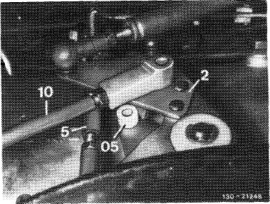
1 Check full throttle stop and adjust at longitudinal regulating shaft, if required.
Force connecting rod (5) from angle lever (1). Disconnect control pressure rod (10). Place adjusting sleeve (05) on stop pin.
|
|||
|
|
|||
|
2 Push angle lever (1) into idle throttle position, so that it will rest against adjusting sleeve (05).
Adjust connecting rod (5) lengthwise in such a manner that it can be pushed in this position free of tension on angle lever (2).
|
-21 ;G
|
||
|
|
|||
|
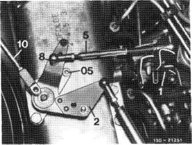
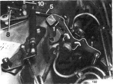
3 Pull anlge lever (1) to full load stop. Loosen ball head (8). Displace in slot until angle lever (1) rests against adjusting sleeve (full load stop). Tighten ball head (8) in this position.
|
 |
||
|
|
|||
|
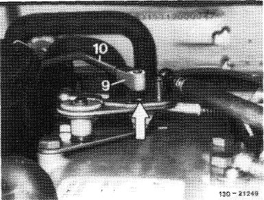
4 In idle throttle position, hold control pressure rod (10) above test bore (arrow) in angle lever (1). Adjust lengthwise at end piece (9) in such a manner that the bore in end piece is in alignment with test bore.
Remove adjusting sleeve (05). Connect control pressure rod (10) and adjust lock.
|
 |
||
|
|
|||
|
30.8-300/8 F 3
|
|||
|
|
|||
|
|
|||||||||||||||||||||||||||||||||||||
|
B. Model 116.120
|
|||||||||||||||||||||||||||||||||||||
|
|
|||||||||||||||||||||||||||||||||||||
|
1978/79 Federal and California version 1980 Federal version
|
|||||||||||||||||||||||||||||||||||||
|
|
|||||||||||||||||||||||||||||||||||||
|
|||||||||||||||||||||||||||||||||||||
|
|
|||||||||||||||||||||||||||||||||||||
 |
1074-8457
|
||||||||||||||||||||||||||||||||||||
|
|
|||||||||||||||||||||||||||||||||||||
|
Connecting rod (5 in Fig. item 4)
|
122
|
||||||||||||||||||||||||||||||||||||
|
|
|||||||||||||||||||||||||||||||||||||
|
Auxiliary tool (spare part)
|
|||||||||||||||||||||||||||||||||||||
|
|
|||||||||||||||||||||||||||||||||||||
|
Adjusting sleeve (5 in Fig. item 5)
|
 |
180 072 03 93
|
|||||||||||||||||||||||||||||||||||
|
|
|||||||||||||||||||||||||||||||||||||
|
30.8-300/9 F 3
|
|||||||||||||||||||||||||||||||||||||
|
|
|||||||||||||||||||||||||||||||||||||
|
|
||||
|
Adjustment
|
||||
|
|
||||
|
1 Check throttle linkage for easy operation and bends. Replace damaged parts, if any.
2 Disconnect all regulating rods.
|
||||
|
|
||||
|
3 Check whether regulating lever (1) of injection pump rests against idle speed stop (3).
4 Check whether connecting rod (5) is correctly set. For this purpose, push regulating lever (1) to full load stop (2). Actuating lever (8) should have max. 0.5 mm play up to full load stop (6). Adjust connecting rod (5) with adjustable ball head (4), if required. Connecting rod (5) should be set to 122 mm, measured from center of ball socket to center of linkage.
|
 |
|||
|
1 Regulating lever
2 Full load stop
3 Idle speed stop
4 Adjustable ball head
5 Connecting rod
6 Full load stop on vacuum control valve
7 Vacuum control valve
8 Actuating lever for vacuum control valve
|
||||
|
|
||||
|
5 Plug-on adjusting sleeve (5).
6 Adjust free travel rod (1) in fully extended condition to 154 mm, measured from center to center of ball head and connect.
|
 |
|||
|
1 Free travel rod
2 Connecting rod
3 Control pressure rod
|
4 Pushrod
5 Adjusting sleeve
6 Regulating lever
|
|||
|
|
||||
|
30.8-300/10 F 3
|
||||
|
|
||||
|
|
|||
|
7 Push regulating lever (1 and 6) against idle speed stop (Fig. item 3 and 6).
8 Adjust pushrod (4) in such a manner that rod can be connected free of tension (Fig. item 5).
9 Move regulating lever (6) to full load. Regulating lever (1) should also rest against full load stop (2) (Fig. item 3 and 6).
|
|||
|
|
|||
|
Adjust adjustable ball head (7) in slot, if required.
|
 |
||
|
3 Control pressure rod
6 Regulating lever
7 Adjustable ball head
|
|||
|
|
|||
|
10 Adjust control pressure rod (3). Regulating lever (6) should rest against idle speed stop. Push control pressure rod carefully against idle stop on transmission, set to tension-free length, connect and secure.
Note: To facilitate assembly, make sure that trademark is facing in upward direction when connecting end piece.
For longitudinal checkup, hold control pressure rod above test bore adjacent to bolt.
|
|||
|
|
|||
|
11 Remove adjusting sleeve (5).
12 Adjust connecting rod (2) to 140 mm, measured from center to center of ball head and connect.
|
 |
||
|
|
|||
|
30.8-300/11 F 3
|
|||
|
|
|||
|
|
|||
|
13 Check full load stop. With engine stopped, push accelerator pedal from inside vehicle up to stop on kickdown switch. Accelerator pedal and regulating lever on injection pump should rest against full load stop. Loosen adjusting screw (arrow), if required, adjust throttle linkage in such a manner that regulating lever rests against full load stop.
|
 |
||
|
|
|||
|
Attention!
If throttle linkage is not moving to full throttle, check whether the contour spring for idle speed adjuster has been correctly installed.
The idle speed adjuster is no longer installed starting model year 1980.
|
1074-5922/2
|
||
|
|
|||
|
If full load or idle speed stop is not attained with this cJjustment, set pull rod (10) from longitudinal regulating shaft to accelerator pedal to 68 mm, measured from center of ball socket to center of damping ring.
If the above adjustment does not attain full load or idle speed stop, set connecting rod (11) from guide lever engine compartment to accelerator pedal to specified length, measured from center to center of ball socket.
|
 |
||
|
10 Pull rod
11 Connecting rod
|
|||
|
|
|||
|
Adjust regulating lever inside vehicle, if required. For this purpose, loosen fastening screw (arrow), pull accelerator pedal slightly upward and tighten fastening screw again.
|
 |
||
|
|
|||
|
30.8-300/12 F 3
|
|||
|
|
|||
|
|
||||||||||||||||||||||||||||||||||||||||||||||||||||||||||||||||||||||||||||||||||||||||||||||||||||||||||
|
14 Adjust Bowden wire for cruise control. For this purpose, push shutoff lever up to stop. Bowden wire should rest free of tension against regulating lever.
If required, adjust Bowden wire by means of adjusting nut (arrow). Release shutoff lever (idle speed position). In this position, Bowden wire has the required play.
|
 |
|||||||||||||||||||||||||||||||||||||||||||||||||||||||||||||||||||||||||||||||||||||||||||||||||||||||||
|
|
||||||||||||||||||||||||||||||||||||||||||||||||||||||||||||||||||||||||||||||||||||||||||||||||||||||||||
|
15 Check operation of emergency stop button. For this purpose, run engine at idle, push emergency stop button (arrow). Engine should stop, adjust pushrod (4), if required.
|
 |
|||||||||||||||||||||||||||||||||||||||||||||||||||||||||||||||||||||||||||||||||||||||||||||||||||||||||
|
|
||||||||||||||||||||||||||||||||||||||||||||||||||||||||||||||||||||||||||||||||||||||||||||||||||||||||||
|
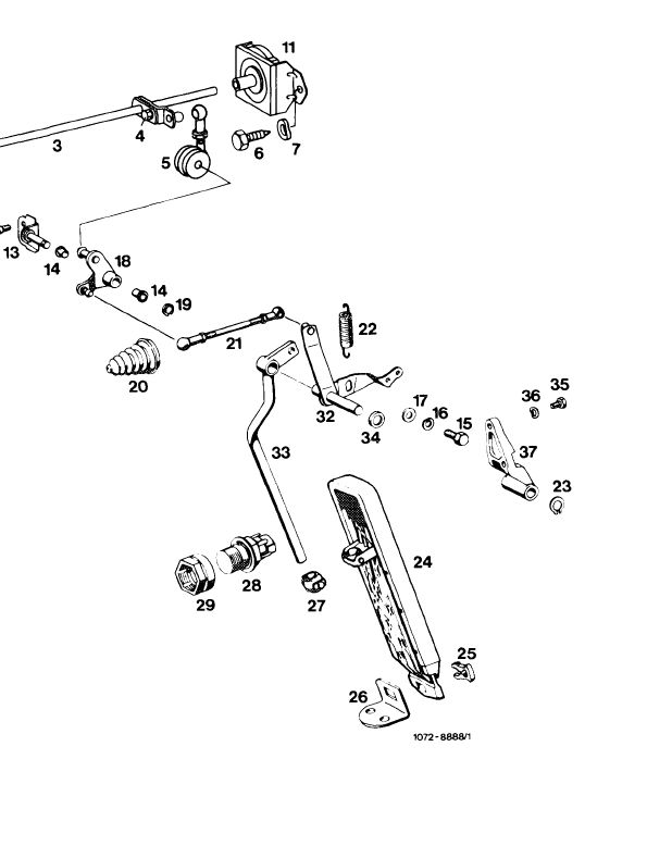
Engine regulation
|
 |
|||||||||||||||||||||||||||||||||||||||||||||||||||||||||||||||||||||||||||||||||||||||||||||||||||||||||
|
||||||||||||||||||||||||||||||||||||||||||||||||||||||||||||||||||||||||||||||||||||||||||||||||||||||||||
|
|
||||||||||||||||||||||||||||||||||||||||||||||||||||||||||||||||||||||||||||||||||||||||||||||||||||||||||
|
30.8-300/13 F 3
|
||||||||||||||||||||||||||||||||||||||||||||||||||||||||||||||||||||||||||||||||||||||||||||||||||||||||||
|
|
||||||||||||||||||||||||||||||||||||||||||||||||||||||||||||||||||||||||||||||||||||||||||||||||||||||||||
|
|
|||||||||||||||||||||||||||||||||||||||||||||||||||||||||||||||||||||||||||||||||||||||||||||||||||||||||||||||||||||||||||||||||||||||||||||||||||||||||||||||||||||||||||
|
Chassis regulation
|
|||||||||||||||||||||||||||||||||||||||||||||||||||||||||||||||||||||||||||||||||||||||||||||||||||||||||||||||||||||||||||||||||||||||||||||||||||||||||||||||||||||||||||
|
|
|||||||||||||||||||||||||||||||||||||||||||||||||||||||||||||||||||||||||||||||||||||||||||||||||||||||||||||||||||||||||||||||||||||||||||||||||||||||||||||||||||||||||||
|
 |
||||||||||||||||||||||||||||||||||||||||||||||||||||||||||||||||||||||||||||||||||||||||||||||||||||||||||||||||||||||||||||||||||||||||||||||||||||||||||||||||||||||||||
|
no longer required starting model year 1980
|
|||||||||||||||||||||||||||||||||||||||||||||||||||||||||||||||||||||||||||||||||||||||||||||||||||||||||||||||||||||||||||||||||||||||||||||||||||||||||||||||||||||||||||
|
|
|||||||||||||||||||||||||||||||||||||||||||||||||||||||||||||||||||||||||||||||||||||||||||||||||||||||||||||||||||||||||||||||||||||||||||||||||||||||||||||||||||||||||||
|
30.8-300/14 F 3
|
|||||||||||||||||||||||||||||||||||||||||||||||||||||||||||||||||||||||||||||||||||||||||||||||||||||||||||||||||||||||||||||||||||||||||||||||||||||||||||||||||||||||||||
|
|
|||||||||||||||||||||||||||||||||||||||||||||||||||||||||||||||||||||||||||||||||||||||||||||||||||||||||||||||||||||||||||||||||||||||||||||||||||||||||||||||||||||||||||
|
|
|||||||||||||||||||||||||||||||||||||||||||||||||||||
|
1980 California version
|
|||||||||||||||||||||||||||||||||||||||||||||||||||||
|
|
|||||||||||||||||||||||||||||||||||||||||||||||||||||
|
Length of regulating rods in mm
|
|||||||||||||||||||||||||||||||||||||||||||||||||||||
|
|
|||||||||||||||||||||||||||||||||||||||||||||||||||||
|
|||||||||||||||||||||||||||||||||||||||||||||||||||||
|
|
|||||||||||||||||||||||||||||||||||||||||||||||||||||
|
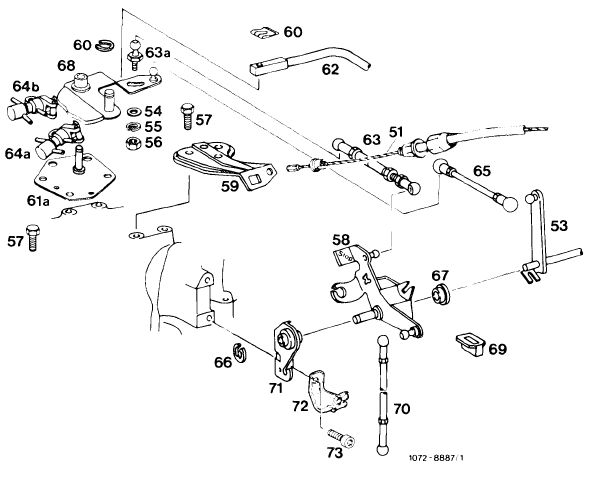
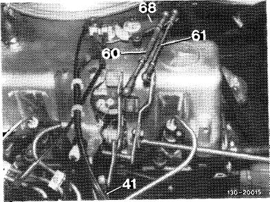
Engine regulation
|
 |
||||||||||||||||||||||||||||||||||||||||||||||||||||
|
51 Bowden wire for cruise control
53 Longitudinal regulating shaft
54 Washer
55 Corrugated washer
56 Nut
57 Screw
58 Angle lever
59 Holder
60 Lock 61a Holder
62 Control pressure rod
63 Free travel rod
63a Screw-type ball head 64a Switchover valve 64b Switchover valve
65 Pull rod
66 Lock
67 Plastic bushing
68 Guide lever
69 Plastic hub
70 Push rod
71 Holder
72 Holder
73 Hex. socket screw
|
|||||||||||||||||||||||||||||||||||||||||||||||||||||
|
|
|||||||||||||||||||||||||||||||||||||||||||||||||||||
|
30.8-300/15 F 3
|
|||||||||||||||||||||||||||||||||||||||||||||||||||||
|
|
|||||||||||||||||||||||||||||||||||||||||||||||||||||
|
|
|||||||||||||||||||||||||||||||||||||||||||||||||||||||||||||||||||||||||||||||||||||||||||||||||||||||||||||||||||||||||||||||||||||||
|
Chassis regulation
|
 |
 |
|||||||||||||||||||||||||||||||||||||||||||||||||||||||||||||||||||||||||||||||||||||||||||||||||||||||||||||||||||||||||||||||||||||
|
|||||||||||||||||||||||||||||||||||||||||||||||||||||||||||||||||||||||||||||||||||||||||||||||||||||||||||||||||||||||||||||||||||||||
|
|
|||||||||||||||||||||||||||||||||||||||||||||||||||||||||||||||||||||||||||||||||||||||||||||||||||||||||||||||||||||||||||||||||||||||
|
Adjustment
|
|||||||||||||||||||||||||||||||||||||||||||||||||||||||||||||||||||||||||||||||||||||||||||||||||||||||||||||||||||||||||||||||||||||||
|
|
|||||||||||||||||||||||||||||||||||||||||||||||||||||||||||||||||||||||||||||||||||||||||||||||||||||||||||||||||||||||||||||||||||||||
|
1 Check regulating linkage for easy operation and bends. Replace damaged parts, if any.
2 Disconnect all regulating rods.
3 Check whether regulating lever (1) of injection pump rests against idle speed stop (3).
|
|||||||||||||||||||||||||||||||||||||||||||||||||||||||||||||||||||||||||||||||||||||||||||||||||||||||||||||||||||||||||||||||||||||||
|
|
|||||||||||||||||||||||||||||||||||||||||||||||||||||||||||||||||||||||||||||||||||||||||||||||||||||||||||||||||||||||||||||||||||||||
|
30.8-300/16 F 3
|
|||||||||||||||||||||||||||||||||||||||||||||||||||||||||||||||||||||||||||||||||||||||||||||||||||||||||||||||||||||||||||||||||||||||
|
|
|||||||||||||||||||||||||||||||||||||||||||||||||||||||||||||||||||||||||||||||||||||||||||||||||||||||||||||||||||||||||||||||||||||||
|
|
|||
|
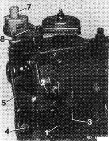
4 Check whether connecting rod (5) is correctly set. For this purpose, push regulating lever (1) to full load stop (2). Actuating lever (8) should have max. 0.5 mm play up to full load stop (6). Adjust connecting rod (5) with adjustable ball head (4), if required. Connecting rod (5) should be set to 122 mm, measured from center of ball socket to center of linkage.
|
■a.*
|
||
|
1 Regulating lever
2 Full load stop
3 Idle speed stop
4 Adjustable ball head
5 Connecting rod
6 Full load stop on vacuum control valve
7 Vacuum control valve
8 Actuating lever for vacuum control valve
|
|||
|
|
|||
|
5 Plug adjusting sleeve on locating pin (arrow) of holder.
6 Set free travel rod (63) in fully extended condition to 154 mm, measured from center to center of ball head and connect.
|
 |
||
|
63 Free travel rod 65 Pull rod 70 Pushrod
|
|||
|
|
|||
|
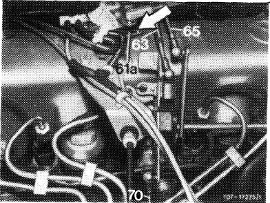
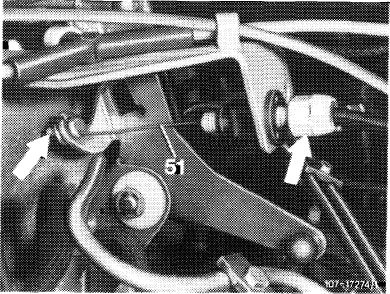
7 Adjust pushrod (70) in such a manner that max. 0.5 mm play is available between control cam lobe of guide lever (68) and link (arrow) of switchover valve (64a). Regulating lever on injection pump should rest against idle speed stop.
|
 |
||
|
62 Control pressure rod
63a Adjustable ball head
64a Switchover valve idle speed shutoff EGR
64b Switchover valve full throttle shutoff EGR
68 Guide lever
60 Lock
|
|||
|
|
|||
|
30.8-300/17 F 3
|
|||
|
|
|||
|
|
|||
|
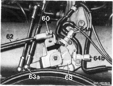
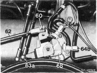
8 Push guide lever (68) in direction of full load. Adjust ball head (63a) in slot of guide lever (68) in such a manner that guide lever rests against adjusting sleeve and regulating lever on injection pump against full load stop.
|
 |
||
|
|
|||
|
9 Adjust control pressure rod (62). Regulating lever on injection pump should rest against idle speed stop (free travel rod should be extended). Carefully push control pressure rod on idle speed stop on transmission.
10 Hold control pressure rod (62) above check bore adjacent to bolt. Adjust end piece lengthwise in such a manner that bore in end piece is in agreement with test bore.
|
|||
|
|
|||
|
11 Connect control pressure rod (62), tighten counter-nut and secure with lock (60).
Note: When connecting end piece, trademark should face in upward direction.
12 Remove adjusting sleeve.
13 Adjust pull rod (65 in Fig. item 5) to 137 mm, measured from center to center of ball head and connect.
|
|||
|
|
|||
|
14 Check full throttle stop. With the engine stopped, push accelerator pedal from inside vehicle up to stop on kickdown switch. Accelerator pedal and regulating lever on injection pump should rest against full throttle stop. Loosen adjusting screw (arrow) if required. Adjust throttle linkage in such a manner that regulating lever rests against full throttle stop.
|
|||
|
|
|||
|
30.8-300/18 F 3
|
|||
|
|
|||
|
|
|||
|
15 If full throttle stop is not attained with this adjustment, set pull rod (5) from longitudinal regulating shaft to accelerator pedal to 68 mm, measured from center of ball socket to center of damping ring.
|
 |
||
|
|
|||
|
16 If the full throttle or idle speed stop is not attained with the above adjustment, set connecting rod (21) from guide lever engine compartment to accelerator pedal to 122 mm, measured from center to center of ball socket. Adjust regulating lever inside vehicle, if required. For this purpose, loosen fastening screw (arrow), pull accelerator pedal slightly up and tighten fastening screw again.
|
 |
||
|
|
|||
|
17 Set Bowden wire for cruise control. For this purpose, push shutoff lever up to stop. Bowden wire should rest free of play against regulating lever.
If required, adjust Bowden wire by means of adjusting screw (arrow). Release shutoff lever (idle speed position). In this position, Bowden wire has the required play (arrow).
|
 |
||
|
51 Bowden wire for cruise control
|
|||
|
|
|||
|
30.8-300/19 F 3
|
|||
|
|
|||
|
|
|||||||||||||||||||||||||||||||||||||||
|
C. Model 123.1, 126.120
|
|||||||||||||||||||||||||||||||||||||||
|
|
|||||||||||||||||||||||||||||||||||||||
|
(usa) starting 1981 Federal and California version
|
|||||||||||||||||||||||||||||||||||||||
|
|
|||||||||||||||||||||||||||||||||||||||
|
|||||||||||||||||||||||||||||||||||||||
|
|
|||||||||||||||||||||||||||||||||||||||
|
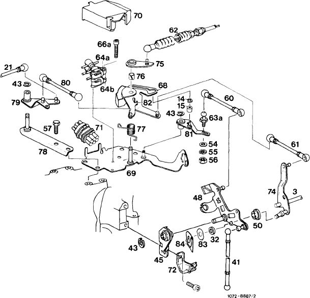
Engine regulation
|
|||||||||||||||||||||||||||||||||||||||
|
|
|||||||||||||||||||||||||||||||||||||||
|
3 Longitudinal regulating shaft
14 Lock
15 Roller
21 Connecting rod for electro cruise control
32 Plastic spacing ring
41 Pushrod
42 Lock
44 Hex. screw
45 Bearing
47 Hex. socket screw
48 Angle lever
50 Plastic bushing
54 Washer
55 Spring washer
56 Nut
57 Screw
60 Pushrod
61 Pull rod
62 Bowden wire for automatic transmission 63a Adjustable ball head
64a Switchover valve idle speed shutoff — EGR 64b Switchover valve full throttle shutoff — EGR
66a Hex. socket screw
68 Guide lever
69 Valve plate
70 Cap
71 Central plug
72 Cable holder
73 Hex. socket screw
73
|
74 Guide lever
75 Drag lever
76 Plastic bushing
77 Spring
78 Holder
79 Guide lever
80 Connecting rod
81 Lever
82 Stop
83 Corrugated washer
84 Lock
|
||||||||||||||||||||||||||||||||||||||
|
|
|||||||||||||||||||||||||||||||||||||||
|
30.8-300/20 F 3
|
|||||||||||||||||||||||||||||||||||||||
|
|
|||||||||||||||||||||||||||||||||||||||
|
|
||||||||||||||||||||||||||||||||||||||||||||||||||||||||||||||||||||||||||||||||||||||||||||||
|
Chassis regulation Model 123.1
|
43
24
|
|||||||||||||||||||||||||||||||||||||||||||||||||||||||||||||||||||||||||||||||||||||||||||||
|
3 Longitudinal regulating shaft
4 Adjusting screw
5 Pushrod
6 Washer
10 Screw
11 Rubber grommet
12 Plastic spacing ring 1 3 Return spring
14 Accelerator pedal lever
18 Hex. screw
19 Corrugated washer
20 Washer
21 Bearing
22 Gasket
24 Accelerator pedal
25 Clip
26 Fastening plate
27 Joint
28 Kickdown switch
29 Adjusting nut
32 Copper netting-graphite disk
33 Lock
34 Regulating lever with damper 34a Conugated washer
|
||||||||||||||||||||||||||||||||||||||||||||||||||||||||||||||||||||||||||||||||||||||||||||||
|
35 Bearing bracket
43 Lock
44 Guide lever
83 Corrugated washer
84 Lock
|
1303-996CV2
|
|||||||||||||||||||||||||||||||||||||||||||||||||||||||||||||||||||||||||||||||||||||||||||||
|
|
||||||||||||||||||||||||||||||||||||||||||||||||||||||||||||||||||||||||||||||||||||||||||||||
|
Model 126.120
|
||||||||||||||||||||||||||||||||||||||||||||||||||||||||||||||||||||||||||||||||||||||||||||||
|
|
||||||||||||||||||||||||||||||||||||||||||||||||||||||||||||||||||||||||||||||||||||||||||||||
 |
||||||||||||||||||||||||||||||||||||||||||||||||||||||||||||||||||||||||||||||||||||||||||||||
|
1072-9126/1
|
|||||||||||||||||||||||||||||||||||||||||||||||||||||||||||||||||||||||||||||||||||||||||||||
|
|
||||||||||||||||||||||||||||||||||||||||||||||||||||||||||||||||||||||||||||||||||||||||||||||
|
30.8-300/21 F 3
|
||||||||||||||||||||||||||||||||||||||||||||||||||||||||||||||||||||||||||||||||||||||||||||||
|
|
||||||||||||||||||||||||||||||||||||||||||||||||||||||||||||||||||||||||||||||||||||||||||||||
|
|
|||
|
Note
Two switchover valves (64a, 64b) are mounted on a valve plate (69) to control EGR. Connection is made by means of a central plug (71). A cap (70) is fitted to prevent dirt from settling on plastic running surface.
|
 |
||
|
64a Switchover valve idle speed shutoff-EGR
64b Switchover valve full throttle shutoff-EGR
68 Guide lever
69 Valve plate
70 Cap
71 Central plug
|
|||
|
|
|||
|
Adjustment
|
|||
|
|
|||
|
1 Check throttle linkage for easy operation and bends. Replace damaged parts.
2 Disconnect all regulating rods and bowden wire (62).
3 Check whether regulating lever (1) of injection pump rests against idle speed stop (3).
|
|||
|
|
|||
|
4 Check whether connecting rod (5) is correctly set. For this purpose, push regulating lever (1) to full throttle stop (2). Actuating lever (8) should have max. 0.5 mm play up to full throttle stop (6). Adjust connecting rod (5) with adjustable ball head (4), if required.
The connecting rod (5) should be set to 122 mm, measured from center of ball socket to center of linkage.
|
 |
||
|
1 Regulating lever
2 Full throttle stop
3 Idle speed stop
4 Adjustable ball head
5 Connecting rod
6 Full throttle stop on vacuum control valve
7 Vacuum control valve
8 Actuating lever for vacuum control valve
|
|||
|
|
|||
|
30.8-300/22 F 3
|
|||
|
|
|||
|
|
|||
|
5 Set pushrod (41) to 184 mm measured from center to center of ball socket and connect.
|
 |
||
|
|
|||
|
6 Adjust guide lever (68):
a) Idle speed position: Set pushrod (60) in such a manner that roller (15) in guide lever (68) rests free of tension against end stop.
b) Full throttle position: Push guide lever (68) to full throttle, roller (15) should have approx. 1 mm distance in guide lever (68).
Set adjustable ball head (63a), if required. When adjusting ball head, readjust pushrod (41). (Fig. engine regulation).
Regulating lever on injection pump should also rest against full throttle stop.
|
|||
|
|
|||
|
7 Check full throttle stop. With engine stopped, step on accelerator pedal from inside vehicle up to stop on kickdown switch. Regulating lever on injection pump should rest against full throttle stop. Loosen adjusting screw (arrow), if required. Set throttle linkage in such a manner that regulating lever rests against full throttle stop.
If full throttle or idle speed stop is not attained with this adjustment, set pushrod (5) from longitudinal regulating shaft to accelerator pedal to 222 mm, measured from center of ball socket to center of damping ring.
|
 |
||
|
|
|||
|
30.8-300/23 F 3
|
|||
|
|
|||
|
|
|||
|
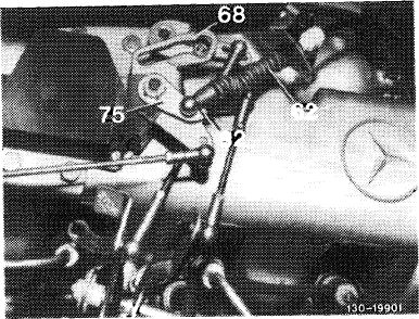
8 Set pull rod (61) to 100 mm, measured from center to center of ball socket and connect.
9 Adjust Bowden wire (62). Guide lever (68) should rest against idle speed stop and drag lever (75) against stop (82). Pull Bowden wire (62) against noticeable idle speed stop on transmission, adjust to tension-free length and connect.
|
 |
||
|
|
|||
|
10 Adjust cruise control. Check whether actuator rests against idle speed stop of cruise control. For this purpose, disconnect connecting rod (21) and push lever of actuator (4) clockwise to idle speed stop. When attaching connecting rod (21), make sure that lever of actuator is pushed away from idle speed stop by approx. 1 mm. Adjust connecting rod, if required.
|
 |
||
|
|
|||
|
30.8-300/24 F 3
|
|||
|
|
|||