Removal and installation of injection nozzles
|
|
|||||
|
07.1—230 Removal and installation of injection nozzles
|
|||||
|
|
|||||
|
Job no. of flat rates or standard texts and flat rates data 07—6810 or 6830.
|
|||||
|
|
|||||
|
Tightening torques
|
Nm
|
||||
|
|
|||||
|
Injection nozzles
|
70-80
|
||||
|
|
|||||
|
Injection lines
|
25
|
||||
|
|
|||||
|
Special tools
|
|||||
|
|
|||||
|
Box wrench socket open, 17 mm, 1/2″ drive for injection lines
|
 |
000 589 68 03 00
|
|||
|
|
|||||
|
Socket for injection nozzle 27 mm, 1/2″ drive
|
 |
001 589 65 09 00
|
|||
|
|
|||||
|
Conventional tools
|
|||||
|
|
|||||
|
Torque wrench 1/2″ drive, 40-130 Nm
|
|||||
|
|
|||||
|
Torque wrench 1/2″ drive, 15—65 Nm
|
|||||
|
|
|||||
|
Removal
|
|||||
|
|
|||||
|
1 Unscrew injection lines.
2 Detach leak-off fuel hoses and plug of 5th injection nozzle.
3 Unscrew injection nozzles using socket. If precombustion chamber collar comes undone, tighten all collars (05-117).
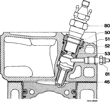
4 Withdraw nozzle plate (53).
5 Sight-check precombustion chamber. Direct flashlight into chamber and examine whether ball pin is in satisfactory condition.
|
 |
||||
|
46 Cylinder head gasket 53 Nozzle plate
50 Collar 80 Injection nozzle
51 Precombustion chamber 81 Pin-type glow plug
52 Sealing ring
|
|||||
|
|
|||||
|
Installation
|
|||||
|
|
|||||
|
6 Install in reverse order, using new nozzle plates. Note tightening torques.
|
|||||
|
|
|||||
|
07.1.8-230/1 F3
|
|||||
|
|
|||||