Replacement of fuel distributor
|
|
||||
|
07.3—205 Replacement of fuel distributor
|
||||
|
|
||||
|
Tightening torques (reference values)
|
Nm
|
|||
|
|
||||
|
Injection lines to fuel distributor
|
||||
|
|
||||
|
Fuel line for cold starting valve to fuel distributor
|
||||
|
|
||||
|
Fuel return line from warm-up compensator to fuel distributor
|
10-12
|
|||
|
|
||||
|
Control pressure line to fuel distributor
|
||||
|
|
||||
|
Control pressure line to pressure damper
|
||||
|
|
||||
|
Injection lines to injection valves
|
10-15
|
|||
|
|
||||
|
Note
|
||||
|
|
||||
|
After stocks of fuel distributor made of gray iron have been used up, only fuel distributors made of light alloy are available as spare parts
Note that for engines 110.984/985/986 they are manufactured with the characteristic of the fuel distributor made of gray casting and without pressure compensating valve. This fuel distributor i s not identical with the light alloy distributor installed in production vehicles (series).
|
||||
|
|
||||
|
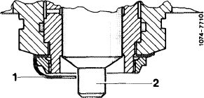
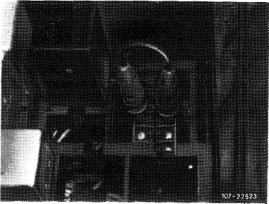
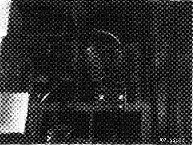
The fuel distributor (gray iron starting Bosch production date 725 and light alloy fuel distributor) is provided with a sheet metal lock (1), which prevents control piston (2) from falling out. The sheet metal lock serves to facilitate assembly, as well as a safety device during transportation, and should not be removed.
|
 |
|||
|
|
||||
|
07.3.2 lla-205/1
|
F 2
|
|||
|
|
||||
|
|
|||
|
Removal
|
 |
||
|
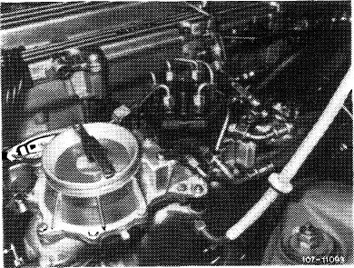
1 Remove air cleaner.
2 Unscrew all fuel and injection lines on fuel distributor and on injection valves. Catch fuel with a rag. Close fuel feed and return line blind.
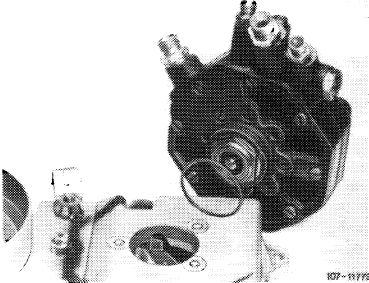
3 Unscrew double thread connection for control pressure line on fuel distributor.
4 Unscrew the three fastening screws on fuel distributor.
5 Remove fuel distributor by turning distributor back and forth.
Attention!
When removing fuel distributor which is not provided with a sheet metal lock, make sure that the control piston is not falling out.
|
|||
|
|
|||
|
Installation
|
 |
||
|
6 Slip new rubber ring on fuel distributor.
7 Slightly lubricate rubber ring and carefully mount fuel distributor.
Attention!
Do not damage rubber ring during assembly, since otherwise false air will be sucked in.
8 Screw-in the three fastening screws on fuel distributor.
|
|||
|
|
|||
|
9 Screw-on double thread connection for control pressure line on fuel distributor.
10 Connect all fuel lines except injection lines.
|
|||
|
|
|||
|
07.3.2 I la-205/2 F2
|
|||
|
|
|||
|
|
|||
|
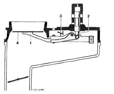
11 Check adjusting lever (1) in air flow sensor and control piston (2) in fuel distributor for easy operation. In addition, on:
|
 |
||
|
Mixture controller with safety switch
Pull plug from safety switch (3), switch-on ignition for a short moment to establish control pressure.
|
|||
|
Mixture controller without safety switch
Pull-off fuel pump relay and bridge the two jacks for a short period to establish control pressure.
Prior to September 1981: Jacks 1 and 2. Starting Spetember 1981: Jacks 7 and 8.
Push air flow sensor plate (4) manually down. A uniform resistance should be felt across entire path. During fast upward movement, no resistance should be felt, since the slowly following control piston lifts from adjusting lever. During a slow upward movement the control piston should follow closely.
|
|||
 |
|||
|
|
|||
|
12 Check association of control piston with air flow sensor plate and adjust, if required. For this purpose, switch-on ignition, pull cable plug from safety switch or pull off fuel pump relay and bridge the two jacks. The fuel should now just stop flowing at output connection to injection lines, adjust association by means of idle speed mixture control screw, if required.
Prior to September 1981: Jacks 1 and 2. Starting September 1981: Jacks 7 and 8.
|
 |
||
|
|
|||
|
13 Mount injection lines.
14 Run engine and check all fuel connections, as well as rubber ring on fuel distributor for leaks by spraying.
15 Adjust idle speed (07.3-100).
|
|||
|
|
|||
|
07.3.2 I la-205/3 F2
|
|||
|
|
|||