Removal and installation of intake manifold, replacement of gasket
|
|
||||
|
14-450 Removal and installation of intake manifold, replacement of gasket
|
||||
|
|
||||
|
Note
|
||||
|
|
||||
|
When removing and installing intake manifold, the mixture controller with air guide housing need not be removed.
|
||||
|
|
||||
|
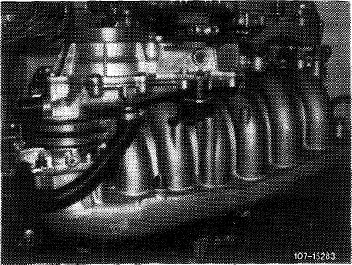
Layout and shape of intake manifold have been changed starting from date of increased output. As a result, the following additional changes were made:
1. Injection lines for cylinders 4—6.
2. Control pressure line from fuel distributor to pressure damper.
3. Control pressure line from warm—up compensator to pressure damper.
4. Return line from warm-up compnesator to fuel distributor.
5. Connection for idle air on air guide housing.
6. Additional holder for supporting mixture controller.
7. Holder for fastening pressure damper to intake manifold.
8. Regulating lever.
9. Air guide housing.
10. Contour hose.
11. Support for intake manifold.
12. Rubber hose for full load enrichment
|
 |
|||
|
|
||||
|
Installation: April 1978
|
||||
|
|
||||
|
Model
|
Starting chassis end No.
|
|||
|
|
||||
|
107.022
107.042
116.024/025
123.033
123.053
123.093
126.022/023
|
005201
004222
113919
039906 (035262) M
008540 (006171 )M
000021
Start of series
|
|||
|
|
||||
|
Righthand steering in England version.
|
||||
|
|
||||
|
14.2 lib—450/1 F2
|
||||
|
|
||||
|
|
|||||||
|
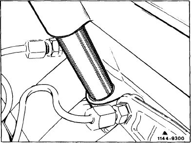
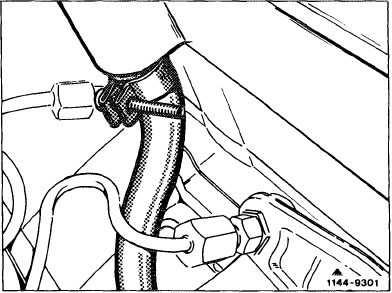
Vent connection to intake manifold Engine 110.984/985/986
Connection has been changed for better distribution of vent vapors. This required a modification of contour hose.
After the former intake manifold has been used up, only the modified intake manifold together with contour hose will be available.
|
 |
||||||
|
1st version
|
|||||||
|
|
|||||||
|
2nd version
|
 |
||||||
|
|
|||||||
|
Installation: September 1979
|
|||||||
|
|
|||||||
|
Model
|
Engine
|
Engine end No.
manual
transmission
|
automatic transmission
|
Chassis end No.
|
|||
|
|
|||||||
|
107.022 107.042
|
110.986
|
003146
|
007150
|
007614 006812
|
|||
|
|
|||||||
|
116.024 116.025
|
110.985
|
014021 069693
|
151315
|
||||
|
|
|||||||
|
123.033 123.053 123.093
|
110.984
|
019774
|
066923
|
064566 017098 004432
|
|||
|
|
|||||||
|
126.022 126.023
|
110.987
|
start of series
|
|||||
|
|
|||||||
|
14.2 llb-450/2 F2
|
|||||||
|
|
|||||||
|
|
||||||||
|
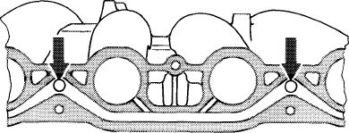
Idle air feed
|
||||||||
|
|
||||||||
|
The idle air feed now proceeds via 2 connections instead of the former central air intake.
Air distribution to the individual cylinders will be improved.
Smooth running of engine following a cold start is also improved by the said measure.
|
 |
|||||||
|
1143-10364
|
||||||||
|
|
||||||||
|
Installation: September 1981
|
||||||||
|
|
||||||||
|
Engine end No. Model Engine manual
transmission
|
automatic transmission
|
Chassis end No.
Installation
mixed
|
Installation continuous
|
|||||
|
|
||||||||
|
107.042 110.990
|
start of series
|
010107-011567 011569
|
||||||
|
|
||||||||
|
123.007 123.033 123.053 123.093
|
110.988
|
start of series
|
085174-096468 096496 024129-024416 024417 010064-010252 010253
|
|||||
|
|
||||||||
|
126.022 126.023
|
110.989
|
start of series
|
021381-043198 043199 039922-042786 042787
|
|||||
|
|
||||||||
|
Removal
|
 |
|||||||
|
1 Remove air cleaner.
2 Drain coolant.
3 Unscrew all fuel and injection lines while catching fuel with a rag. Close fuel lines blind.
|
||||||||
|
1 st version
|
||||||||
|
|
||||||||
|
4 Pull cable plug from mixture controller (if installed) and from cold start valve.
5 Disconnect connecting rod for longitudinal regulating shaft. On model 126, remove longitudinal regulating shaft (30-310).
6 Pull off vacuum line for automatic transmission and central locking system.
7 Unscrew cable strap for electric cable harness (cold start valve, warm-up compensator, safety switch).
2nd version
|
 |
|||||||
|
|
||||||||
|
14.2 llb-450/3 F2
|
||||||||
|
|
||||||||
|
|
|||
|
8 Remove heater hose from dashboard.
9 Pull off vacuum line for ignition timing.
|
|||
|
|
|||
|
10 Unscrew line for diagnosis plug.
|
|||
|
|
|||
|
11 Unscrew vacuum line for brake unit.
|
|||
|
|
|||
|
12 Remove decel shutoff valve.
|
 |
||
|
3rd version
with decel shutoff
|
|||
|
|
|||
|
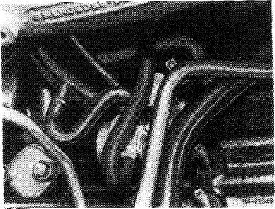
13 Pull off contour hoses after loosening hose clamp and leak line on idle air distributor.
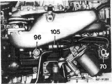
14 On engines prior to increased output, unscrew control pressure line on diaphragm damper (105) and return flow line on warm-up compensator (70).
On model 126, unscrew high-pressure oil line for power steering pump.
|
 |
||
|
|
|||
|
15 Unscrew all fastening nuts and screws on intake manifold as well as on support.
|
 |
||
|
|
|||
|
14.2 Mb—450/4 F2
|
|||
|
|
|||
|
|
||
|
16 Unscrew both fastening screws for engine mounts and engine clamper. Lift engine with pitlift until intake manifold can be taken off.
On model 126, pull engine to the right and remove intake manifold.
17 Clean intake manifold and check flange faces with straightedge, refinish on surface plate, if required.
|
||
|
|
||
|
Installation
|
||
|
|
||
|
18 For installation proceed vice versa, using a new gasket.
Prior to tightening intake manifold, introduce return flow line from warm-up compensator.
19 Tighten fastening screws for engine mounts to 75 Nm.
20 Fill-in coolant.
21 Adjust regulating linkage (30-300). Check for easy operation.
22 Run engine, check fuel lines for leaks. Check intake system, fuel distributor and injection valves for leaks by spraying with Iso-Oktan or benzine.
23 Adjust idle speed (07.3-100).
|
||
|
|
||
|
14.2 llb-450/5 F2
|
||
|
|
||
|
|
|||||||||||||||||||||||||||||||||||||||||||||||||||||||||||||||||||||||||||||||||||||||||||||||||||||||||||||||||||
|
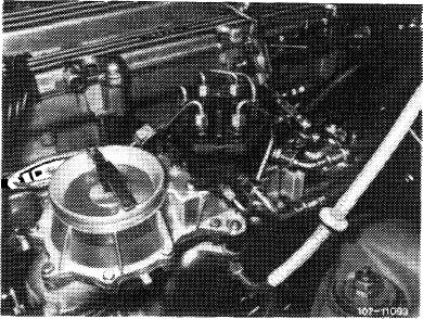
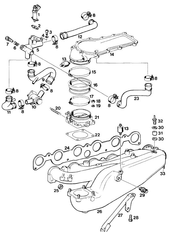
Intake manifold
1st version
up to increased output
|
 |
||||||||||||||||||||||||||||||||||||||||||||||||||||||||||||||||||||||||||||||||||||||||||||||||||||||||||||||||||
|
|||||||||||||||||||||||||||||||||||||||||||||||||||||||||||||||||||||||||||||||||||||||||||||||||||||||||||||||||||
|
|
|||||||||||||||||||||||||||||||||||||||||||||||||||||||||||||||||||||||||||||||||||||||||||||||||||||||||||||||||||
|
14.2 llb-450/6 F2
|
|||||||||||||||||||||||||||||||||||||||||||||||||||||||||||||||||||||||||||||||||||||||||||||||||||||||||||||||||||
|
|
|||||||||||||||||||||||||||||||||||||||||||||||||||||||||||||||||||||||||||||||||||||||||||||||||||||||||||||||||||
|
|
||||||||||||||||||||||||||||||||||||||||||||||||||||||||||||||||||||||||||||||||||||||||||||||||||||||||||||||||||||||||||||||||||||||||||
|
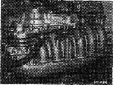
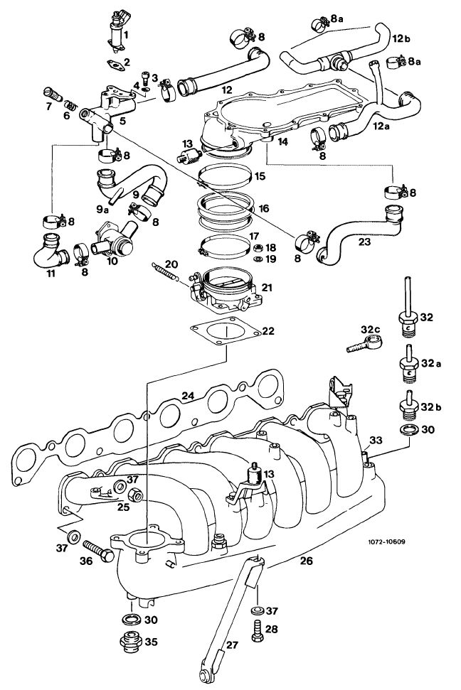
2nd version
starting with increased
|
||||||||||||||||||||||||||||||||||||||||||||||||||||||||||||||||||||||||||||||||||||||||||||||||||||||||||||||||||||||||||||||||||||||||||
|
|
||||||||||||||||||||||||||||||||||||||||||||||||||||||||||||||||||||||||||||||||||||||||||||||||||||||||||||||||||||||||||||||||||||||||||
 |
||||||||||||||||||||||||||||||||||||||||||||||||||||||||||||||||||||||||||||||||||||||||||||||||||||||||||||||||||||||||||||||||||||||||||
|
|
||||||||||||||||||||||||||||||||||||||||||||||||||||||||||||||||||||||||||||||||||||||||||||||||||||||||||||||||||||||||||||||||||||||||||
|
||||||||||||||||||||||||||||||||||||||||||||||||||||||||||||||||||||||||||||||||||||||||||||||||||||||||||||||||||||||||||||||||||||||||||
|
|
||||||||||||||||||||||||||||||||||||||||||||||||||||||||||||||||||||||||||||||||||||||||||||||||||||||||||||||||||||||||||||||||||||||||||
|
14.2 llb-450/7 F2
|
||||||||||||||||||||||||||||||||||||||||||||||||||||||||||||||||||||||||||||||||||||||||||||||||||||||||||||||||||||||||||||||||||||||||||
|
|
||||||||||||||||||||||||||||||||||||||||||||||||||||||||||||||||||||||||||||||||||||||||||||||||||||||||||||||||||||||||||||||||||||||||||