Removal and installation of fuel tank model 114
|
|
||||||||||||||||||||||||||||||||||||||||||||||||||||||||||
|
47—700 Removal and installation of fuel tank
|
||||||||||||||||||||||||||||||||||||||||||||||||||||||||||
|
|
||||||||||||||||||||||||||||||||||||||||||||||||||||||||||
|
A. Model 114
|
||||||||||||||||||||||||||||||||||||||||||||||||||||||||||
|
|
||||||||||||||||||||||||||||||||||||||||||||||||||||||||||
|
Filling capacity in liters
|
1975/76
|
|||||||||||||||||||||||||||||||||||||||||||||||||||||||||
|
|
||||||||||||||||||||||||||||||||||||||||||||||||||||||||||
|
||||||||||||||||||||||||||||||||||||||||||||||||||||||||||
|
|
||||||||||||||||||||||||||||||||||||||||||||||||||||||||||
|
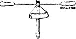
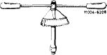
Clamp for fuel hose
|
 |
000 589 40 37 00
|
||||||||||||||||||||||||||||||||||||||||||||||||||||||||
|
|
||||||||||||||||||||||||||||||||||||||||||||||||||||||||||
|
Torque wrench, double arm, 1/2″ square, 15-65 Nm (150-650 kpcm)
Torque wrench, double arm, 1/4″ square, 4-16 Nm (40-160 kpcm)
|
 |
000 589 27 21 00
|
||||||||||||||||||||||||||||||||||||||||||||||||||||||||
|
000 589 67 21 00
|
||||||||||||||||||||||||||||||||||||||||||||||||||||||||||
|
|
||||||||||||||||||||||||||||||||||||||||||||||||||||||||||
|
Attention!
When removing fuel tank, pay attention to safety rules.
|
||||||||||||||||||||||||||||||||||||||||||||||||||||||||||
|
|
||||||||||||||||||||||||||||||||||||||||||||||||||||||||||
|
Removal
|
 |
|||||||||||||||||||||||||||||||||||||||||||||||||||||||||
|
1 Disconnect ground line on battery.
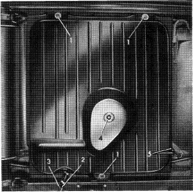
2 Drain fuel tank while unscrewing fuel drain plug (4 in fig. item 5).
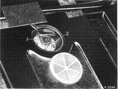
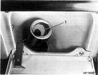
3 Pull coupler (1) for fuel readout from immersion tube transmitter (2).
|
||||||||||||||||||||||||||||||||||||||||||||||||||||||||||
|
|
||||||||||||||||||||||||||||||||||||||||||||||||||||||||||
|
47.2 lb-700/1
|
||||||||||||||||||||||||||||||||||||||||||||||||||||||||||
|
|
||||||||||||||||||||||||||||||||||||||||||||||||||||||||||
|
|
|||
|
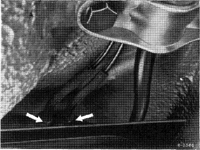
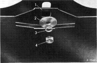
4 Pull off positive and negative venting line on fuel tank (arrows).
|
 |
||
|
|
|||
|
5 Pinch fuel hoses (2 and 3) with a clamp. Loosen hose clips and pull fuel hoses from fuel tank.
6 Loosen fastening nuts (1) and remove fuel tank.
|
 |
||
|
|
|||
|
Installation
|
 |
||
|
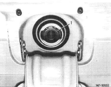
Due to the small fuelling guns for lead-free fuel (catalyst operation) on these vehicles, specified in the USA starting model year 1975, a guide funnel (1) is installed in filler neck.
|
|||
|
|
|||
|
47.2 lb-7OO/2
|
|||
|
|
|||
|
|
|||
|
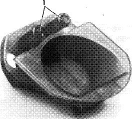
If a fuel tank is replaced on these vehicles, install a guide funnel in the USA only. For this purpose, place guide funnel into filler neck prior to installation of fuel tank and knock-in fastening rivets up to stop by means of a punch.
|
 |
||
|
|
|||
|
1 Fastening rivets
|
M7-KXK?
|
||
|
|
|||
|
Install fuel tank in reverse order. Pay attention to the following items:
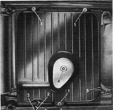
7 Mount fuel tank with reinforcing panels (1) and washers (2) provided.
If the reinforcing panels are left out or the washers used are too small, the holding brackets on fuel tank may be torn off.
|
 |
||
|
|
|||
|
8 Check whether foam rubber strips on fuel tank are tight and glue down with MB universal glue part no. 000 989 92 71, if required.
Note: Never use felt or similar material, since this may lead to corrosion damage.
|
|||
|
|
|||
|
9 Tighten the three fastening nuts (1) to 20-25 Nm (2-2.5 kpm). When using self-locking nuts, tighten to 26-34 Nm (2.6-3.4 kpm).
|
 |
||
|
|
|||
|
47.2 lb-700/3
|
|||
|
|
|||
|
|
||||||||||||||||||||||||||||||||||||
|
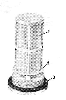
10 Blow out strainer jacket (1) of fuel drain plug and check for damage. Install closing plug and tighten to 35-43 Nm (3.5-4.3 kpm).
Note: The filter is made of square mesh fabric of 0.1 mm mesh width. To prevent mixing up closing plug, the word „diesel” is punched-in on diesel engines.
11 Connect ground line to battery. Check function of fuel readout.
|
 |
|||||||||||||||||||||||||||||||||||
|
|
||||||||||||||||||||||||||||||||||||
|
K-U30
|
||||||||||||||||||||||||||||||||||||
|
|
||||||||||||||||||||||||||||||||||||
|
B. Model 116
|
||||||||||||||||||||||||||||||||||||
|
|
||||||||||||||||||||||||||||||||||||
|
||||||||||||||||||||||||||||||||||||
|
|
||||||||||||||||||||||||||||||||||||
|
Clamp for fuel hose
|
 |
000 589 40 37 00
|
||||||||||||||||||||||||||||||||||
|
|
||||||||||||||||||||||||||||||||||||
|
Torque wrench, double arm, 1/2″ square 15-65 Nm (150-650 kpcm)
|
 |
000 589 27 21 00
|
||||||||||||||||||||||||||||||||||
|
|
||||||||||||||||||||||||||||||||||||
|
47.2 lb-700/4
|
||||||||||||||||||||||||||||||||||||
|
|
||||||||||||||||||||||||||||||||||||
|
|
|||
|
Attention!
When removing fuel tank, pay attention to safety rules.
|
 |
||
|
Removal
|
|||
|
1 Disconnect ground line on battery.
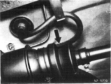
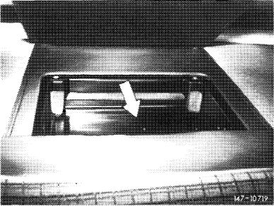
2 Drain fuel tank. For this purpose, pinch fuel suction hose (arrow) with clamp. Loosen hose clamp on fuel feed line, pull off hose and drain fuel.
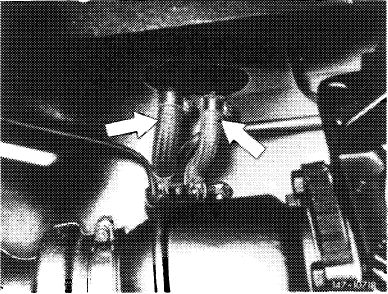
3 Loosen hose clamps on fuel return hose and fuel tank vent hose (arrows) and pull hoses from fuel tank.
|
|||
|
|
|||
 |
|||
|
|
|||
|
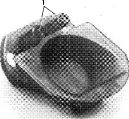
4 Remove first aid kit and first aid kit mounting tray (arrow).
|
 |
||
|
|
|||
|
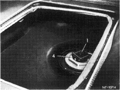
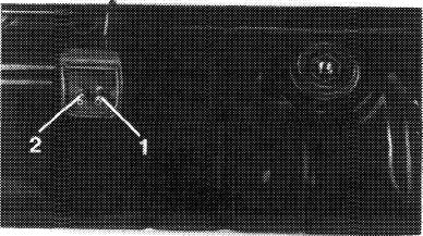
5 Pull coupler (1) for fuel readout from immersion tube transmitter (4) and protect against slipping off with a wire.
|
 |
||
|
|
|||
|
47.2 lb-700/5
|
|||
|
|
|||
|
|
|||
|
6 Remove rear wall for fuel tank cover.
|
 |
||
|
|
|||
|
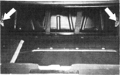
7 Unscrew fuel tank fastening nuts (arrows) and remove fuel tank.
|
 |
||
|
|
|||
|
U7- 10715
|
|||
|
|
|||
|
Installation
|
 |
||
|
<©) 1975/76 only
Due to the small fuelling guns for lead-free fuel (catalyst operation) on these vehicles, specified in the USA starting model year 1975, a guide funnel (1) is installed in filler neck.
|
|||
|
|
|||
|
If a fuel tank is replaced on these vehicles, install a guide funnel in the USA only. For this purpose, place guide funnel into filler neck prior to installation of fuel tank and knock-in fastening rivets up to stop by means of a punch.
|
 |
||
|
1 Fastening rivets
|
|||
|
|
|||
|
47.2 lb-700/6
|
|||
|
|
|||
|
|
|||
|
8 Install fuel tank in reverse order as follows:
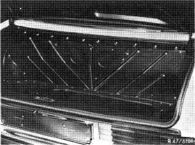
a) Glue both gaskets to bottom of fuel tank with MB universal glue, part no. 000 989 92 71. For installation, coat both gaskets on sealing surface or bead with sliding agent (talcum, wax or the like).
|
 |
||
|
|
|||
|
1 Positive and negative vent line
2 Fuel return line
|
M7- 16744
|
||
|
|
|||
|
b) Check whether foam rubber strips on fuel tank are tight; if required, glue down for example with MB universal glue, part no. 000 989 92 71.
c) Mount fuel tank with specified reinforcing panels and washers. Tighten fastening nuts to 20-25 Nm (2-2.5 kpm). When using self-locking nuts, tighten to 26-34 Nm (2.6-3.4 kpm).
d) Pay attention to correct seat of rubber sleeve on filler neck.
e) Mount coupler for fuel readout and check for function.
|
|||
|
|
|||
|
47.2 lb-700/7
|
|||
|
|
|||