Checking suction valve and delivery valves of accelerating pump for leaks
|
|
|||
|
07.2—152 Checking suction valve and delivery valves of accelerating pump for leaks
|
|||
|
|
|||
|
Self-made tool
|
|||
|
|
|||
|
Puller
|
refer to Fig. item 1
|
||
|
|
|||
|
Note
|
|||
|
|
|||
|
With a leaking suction valve, fuel is pushed back into float chamber during delivery stroke and the quantity of the injected fuel is reduced. This may result in starting and bypass faults particularly during slow acceleration. If the delivery valves are leaking, air is drawn in during suction stroke which will also reduce the quantity of the injected fuel.
|
|||
|
|
|||
|
Checking suction valve for leaks
|
 |
||
|
1 Remove carburetor cover (07.2—192).
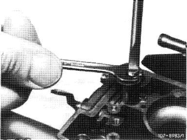
2 Check suction valve for leaks. For this purpose, pull out closing plug for suction duct of accelerating pump by means of a self-made puller.
Attention!
Closing plugs without threads should be drilled 4 mm deep by means of a 3 mm drill and provided with M 4 metric threads. Carefully cover area around drilled hole first.
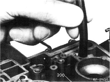
3 Fill float chamber with fuel, slip suitable hose over suction duct.
|
|||
 |
|||
|
200 Suction bore
|
|||
|
|
|||
|
07.2.2 la—152/1
|
|||
|
|
|||
|
|
|||
|
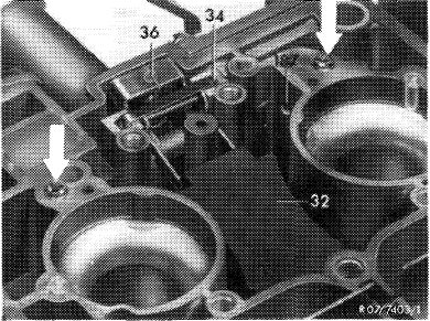
4 Keep both delivery valves (arrow) closed, on carburetors with negative vent bore (187) also keep this bore closed and blow into hose. No or only individual bubbles should come out of suction bore and enter float chamber.
Attention!
In the event of a leaking suction valve seat, knock lightly against seat with a steel ball (5 mm dia.). Insert new steel ball and check once again for leaks. Then close suction duct.
|
 |
||
|
|
|||
|
Checking delivery valves for leaks
|
 |
||
|
5 For this purpose, slip suitable hose over a delivery valve, keep other delivery valve closed, on carburetors with negative vent bore (187) keep this bore also closed and blow into hose. No or only individual air bubbles should come out of suction bore (200) and enter float chamber.
Attention!
In the event of leaks, knock lightly against balls of delivery valves on their seat.
|
|||
|
|
|||
|
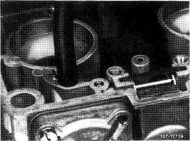
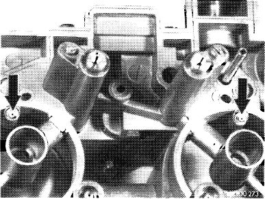
6 Blow out injection bores (arrows) of accelerating pump with compressed air and check for unobstructed passage (clean injection bores with a 0.5 mm drill, if required).
7 Mount carburetor cover with new gasket (07.2— 192).
8 Adjust accelerating pump (07.2—150).
|
 |
||
|
Arrows = injection jets
|
|||
|
|
|||
|
07.2.2 la-152/2
|
|||
|
|
|||