Adjusting accelerating pump
|
|
||||
|
07.2—150 Adjusting accelerating pump
|
||||
|
|
||||
|
Testing and adjusting values
|
||||
|
|
||||
|
Begin of injection
|
immediately
|
|||
|
|
||||
|
Special tool
|
||||
|
|
||||
|
Clamp
|
 |
000 589 40 37 00
|
||
|
|
||||
|
Note
|
||||
|
|
||||
|
Perfect functioning of accelerating pump as well as accurate adjustment of pump are absolutely necessary for perfect starting or bypass characteristics. Starting and bypass faults may be caused by a wrong direction of injection jet, the jet should not touch neither the pre-atomizer nor the edge of the Venturi. Unless otherwise specified, injection should begin immediately. If the injected quantity is too low, bypass faults may occur in stage I and from stage I — II (stage jump).
|
||||
|
|
||||
|
Testing, adjusting
|
 |
|||
|
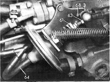
a) Begin of injection
1 Keep engine running. Pinch vacuum hose (64), shut off engine.
2 Check whether throttle valve lever (3) is resting against idle speed adjusting screw (68) and adjust vacuum governor, if required.
|
||||
|
|
||||
|
07.2.2 la-150/1
|
||||
|
|
||||
|
|
|||
|
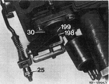
3 Set adjusting nut (25) in such a manner that the actuating lever (198) depresses the diaphragm pressure pin (199) by 1.0 mm.
Note: If no self-locking polystop adjusting nut (25) is installed, secure adjusting nut following adjustment by compressing (pinching) nut.
|
 |
||
|
|
|||
|
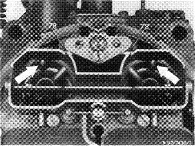
b) Operation and direction of injection
4 For this purpose, slowly actuate throttle valve lever, so that a uniform fuel jet will come out of both injection bores (arrows) immediately and on both sides.
Attention!
The fuel jet should not touch edge of Venturi and pre-atomizer, since this may result in starting and bypass faults. If required, remove carburetor cover and clean injection bores.
|
 |
||
|
|
|||
|
07.2.2 la-150/2
|
|||
|
|
|||