Removal and installation of pulley, vibration damper and balancing disc
|
|
|||||||||||||||||||||||||||||||||||||||||||||||||
|
03—340 Removal and installation of pulley, vibration damper and balancing disc
|
|||||||||||||||||||||||||||||||||||||||||||||||||
|
|
|||||||||||||||||||||||||||||||||||||||||||||||||
|
|||||||||||||||||||||||||||||||||||||||||||||||||
|
|
|||||||||||||||||||||||||||||||||||||||||||||||||
|
Torque wrench 150—500 IMm (15—50 kpm), 3/4″ square
|
 |
001 589 31 21 00
|
|||||||||||||||||||||||||||||||||||||||||||||||
|
|
|||||||||||||||||||||||||||||||||||||||||||||||||
|
Detent
|
 |
110 589 00 40 00 or
|
|||||||||||||||||||||||||||||||||||||||||||||||
|
|
|||||||||||||||||||||||||||||||||||||||||||||||||
|
Detent
|
 |
116 589 01 40 00
|
|||||||||||||||||||||||||||||||||||||||||||||||
|
|
|||||||||||||||||||||||||||||||||||||||||||||||||
|
Puller for balancing disc
|
 |
116 589 10 33 00
|
|||||||||||||||||||||||||||||||||||||||||||||||
|
|
|||||||||||||||||||||||||||||||||||||||||||||||||
|
Note
|
 |
||||||||||||||||||||||||||||||||||||||||||||||||
|
The vibration damper can be replaced without balancing.
If the balancing disc is renewed, static balancing is required (03—344).
Since May 1974 a balancing disc with 3 cutouts for removing tensioning rail bearing bolt is installed.
|
|||||||||||||||||||||||||||||||||||||||||||||||||
|
|||||||||||||||||||||||||||||||||||||||||||||||||
|
|
|||||||||||||||||||||||||||||||||||||||||||||||||
|
03.2-340/1 F 3
|
|||||||||||||||||||||||||||||||||||||||||||||||||
|
|
|||||||||||||||||||||||||||||||||||||||||||||||||
|
|
|||
|
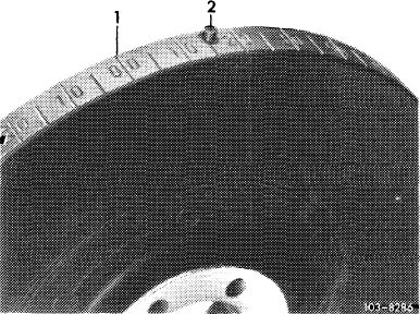
Attention!
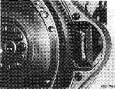
For engines which have a „0/0” mark for BDC on the vibration damper besides TDC, the TDC mark in the vibration damper is next to the pin.
|
 |
||
|
|
|||
|
Removal
|
 |
||
|
1 Remove radiator and fan.
|
|||
|
2 Remove pulley and vibration damper.
|
|||
|
|
|||
|
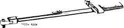
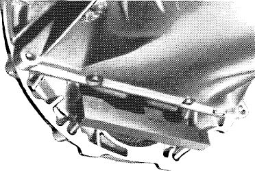
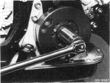
3 Counterhold crankshaft with holder.
|
 |
||
|
|
|||
|
Holder 110 589 00 40 00
|
103-9243
|
||
|
|
|||
|
Also remove starter of engines with a manual transmission.
|
 |
||
|
Holder 116 589 01 40 00
|
|||
|
|
|||
|
03.2-340/2
|
|||
|
|
|||
|
|
|||
|
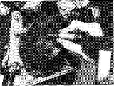
4 Remove bolt in crankshaft.
|
 |
||
|
|
|||
|
5 Mark balance disc and crankshaft together with a punch mark.
|
 |
||
|
|
|||
|
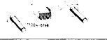
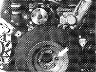
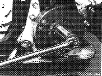
6 Pull off balance disc with an extractor.
|
103-8363
|
||
|
|
|||
|
Installation
|
|||
|
|
|||
|
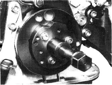
7 Install balance disc on crankshaft that bores for dowel pins align.
Note: The balance disc is located on the crankshaft by two offset dowel pins.
|
|||
|
|
|||
|
03.2-340/3
|
|||
|
|
|||
|
|
|||||||||||||||||||||||||||||||
|
8 Pull balancing disc on crankshaft with screw M 18 x 1.5 x 45 and a cup spring.
9 Knock-in both set pins.
|
 |
||||||||||||||||||||||||||||||
|
|
|||||||||||||||||||||||||||||||
|
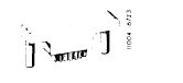
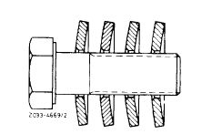
10 Mount four cup springs with convex face facing screw head.
11 Tighten screw on crankshaft to 400 Nm
while applying counterhold to crankshaft by means of detent.
Note: Damaged threads M 18 x 1.5 in crankshaft journal at the front can be repaired by inserting a helicoil insert 0130 0184027.
12 Install vibration damper, pulley, viscofan and
radiator.
|
 |
||||||||||||||||||||||||||||||
|
|
|||||||||||||||||||||||||||||||
|
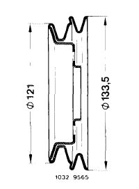
Note: Take association of pulley on crankshaft for various engines 110 from the following list.
|
|||||||||||||||||||||||||||||||
|
|
|||||||||||||||||||||||||||||||
|
 |
||||||||||||||||||||||||||||||
|
|
|||||||||||||||||||||||||||||||
|
03.2 340/4 F 3
|
|||||||||||||||||||||||||||||||
|
|
|||||||||||||||||||||||||||||||
|
|
||||||
|
Pulley
|
Engine
|
 |
||||
|
|
||||||
|
110 466 01 15
|
110.921*
|
|||||
|
110.931* 110.922 version 1 110.032 version 1 110.981* 110.991* 110.982 110.992 110.983 110.993 with special version power steering or air conditioning
|
||||||
|
|
||||||
|
110466 01 15
|
||||||
|
|
||||||
|
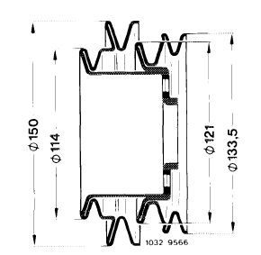
Pulley
|
Engine
110.922 version 2 110.932 version 2
110.923 version 1*
110.924 version 1* 110.984 version 1* 110.985 110.986
110.987 versioni* 110.994
|
 |
||||
|
123 032 00 04
|
||||||
|
* with 55 Ah alternator
|
||||||
|
|
||||||
|
123 032 00 04
|
||||||
|
|
||||||
|
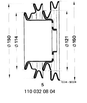
Pulley
|
Engine
|
 |
||||
|
|
||||||
|
123 032 01 04
|
110.922*
|
|||||
|
110.932* 110.923* 110.924* 110.984* 110.985* 110.986* 110.987* 110.994* * with special version air conditioning or emission control
|
||||||
|
|
||||||
|
Pulley 110 032 08 041)
Introduction into series C^)August 1978
starting engine end no. starting chassis end no.
|
123 032 01 04
|
|||||
 |
||||||
|
110.984-12-043 370 110.985-12-044 308
Introduction into seriesCA
|
123.033-12-043 906 123.053-12-010 554
|
|||||
|
starting engine end no. starting chassis end no.
123.0072) 110.984 -„”0-023 276 123.033 019 600
|
||||||
|
-12-076 809
|
123.053
|
|||||
|
110.985-12-075 271 116.024-157 385
1) Together with 65 Ah alternator
2) (s) only
|
||||||
|
|
||||||
|
03.2-340/5 F 3
|
||||||
|
|
||||||
|
|
|||||||
|
Pulley 110 032 09 04* (formerly 123 032 00 04)
Introduction into series March 1980
starting engine end no. starting chassis end no.
1log23-10-014 965 123.030-029 250 -12-018 195 123.050-003 705
|
 |
||||||
|
|
o
CO
|
||||||
|
eg
|
|||||||
|
|
|||||||
|
110.924
|
-10-000 356 -12-001 102
|
126.021-001 320
|
|||||
|
|
|||||||
|
110984 -10-023 276 123.033-073 349 -12-076 809 123.053-019 600
110.985 -12-075 271 126.024/025-157 385
110.987 ~1 °-°00 675 126.022/023-004 070 -12-003 696
* together with 65 Ah alternator
|
 |
||||||
|
1034 9208
|
|||||||
|
|
|||||||
|
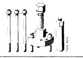
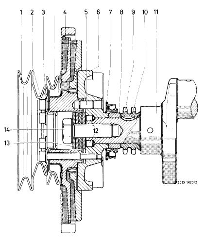
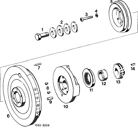
Pulleys, vibration damper and balancing disc
|
|||||||
|
|
|||||||
|
1 Screw M 18 x 1.5 x 45
2 Cup springs
3 6 screws M 8 x 65
4 6 washers 8.4
5 Pulley
6 Vibration damper 254 mm dia
7 Adjustment indicator
8 2 set pins 8×8
9 Cyl. pin 10h8x 18
10 Balancing disc
11 Radial sealing ring 1 2 Spacing ring
13 Crankshaft gear
14 Woodruff key
|
 |
||||||
|
|
|||||||
|
03.2-340/6 F2
|
|||||||
|
|
|||||||