Checking, replacing and tightening conrod bolts
|
|
|||||||||||||||||||||||||||||||||||||||||||||||||
|
03—310 Checking, replacing and tightening conrod bolts
|
|||||||||||||||||||||||||||||||||||||||||||||||||
|
|
|||||||||||||||||||||||||||||||||||||||||||||||||
|
Conrod bolt sizes
|
|||||||||||||||||||||||||||||||||||||||||||||||||
|
|
|||||||||||||||||||||||||||||||||||||||||||||||||
|
|||||||||||||||||||||||||||||||||||||||||||||||||
|
|
|||||||||||||||||||||||||||||||||||||||||||||||||
|
Conrod bolt installation pressure
|
45000 N
|
||||||||||||||||||||||||||||||||||||||||||||||||
|
|
|||||||||||||||||||||||||||||||||||||||||||||||||
|
|||||||||||||||||||||||||||||||||||||||||||||||||
|
|
|||||||||||||||||||||||||||||||||||||||||||||||||
|
Checking
|
 |
||||||||||||||||||||||||||||||||||||||||||||||||
|
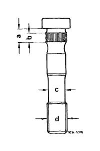
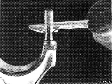
1 Measure smallest expansion stem diameter before reusing.
|
|||||||||||||||||||||||||||||||||||||||||||||||||
|
|
|||||||||||||||||||||||||||||||||||||||||||||||||
|
03.2-310/1 F3
|
|||||||||||||||||||||||||||||||||||||||||||||||||
|
|
|||||||||||||||||||||||||||||||||||||||||||||||||
|
|
|||
|
Note: If the minimum expansion stem diameter reaches or is less than 8.0 mm, replace conrod bolt.
Only knock out a conrod bolt to replace it. Use third version conrod bolts for repairs.
|
 |
||
|
|
|||
|
Replacing
|
 |
||
|
2 Knock out conrod bolts.
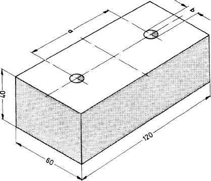
3 Press new bolts into conrod with a pressure of about 45000 N, or knock in with a hammer and mandrel.
Place the connecting rod on a ground steel plate when knocking in or pressing in conrod bolts.
|
|||
|
Distance between holes a = 64.6 mm Bore b = 11 mm
|
|||
|
|
|||
|
Tightening
|
|||
|
|
|||
|
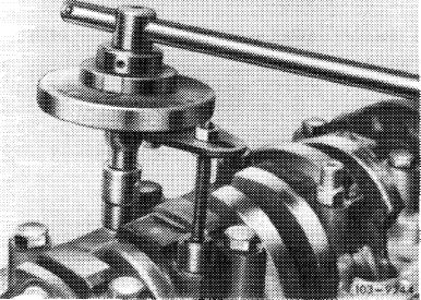
4 Lubricate nuts and threads.
5 Tighten conrod nuts to a torque pressure of 40-50 Nm and a torque angle of 90-100°.
Attention!
Tighten conrod bolts knocked in with a hammer to a torque pressure of 60—70 Nm and a torque angle of 90-100° for the first time.
|
 |
||
|
|
|||
|
03.2-310/2 F3
|
|||
|
|
|||
|
|
||
|
Make sure that this instruction is observed, since otherwise the nuts of the conrod bolts may become loose.
Note: If no angle of rotation wrench is available, the connecting rod nuts can also be tightened by means of a normal socket wrench with toggle in one step by an angle of 90—100°. Estimate angle as accurately as possible. To eliminate angle faults, do not use a torque wrench for tightening according to angles of rotation.
|
||
|
|
||
|
03.2-310/3 F3
|
||
|
|
||