Engine ventilation — Functional description
WIS 00-310
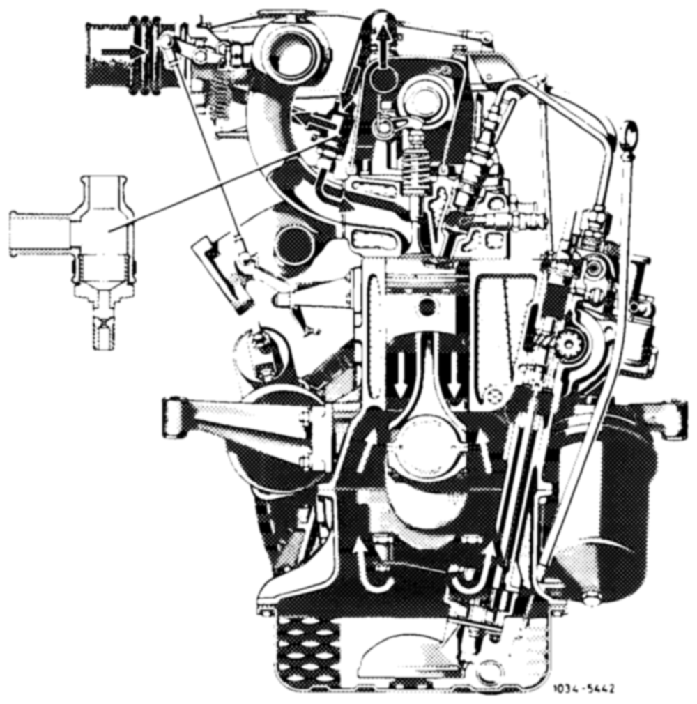
The engine ventilation systen is closed and maintenance-free.
Engines 615, 616
Injection pump with pneumatic governor
Engine blow-by gases and crankcase vapors flow through the connecting ports in the valve cover, reaching the water separator and by-pass bore at the rear pair of intake pipes. At low and medium duty — giving a high intake pipe vacuum and a low ventilation rate — the gases, vapors and condensate pass through the by-pass bores (1.3 mm in diameter) at the front and rear pairs of intake pipes, flowing straight into the intake ports (arrows).
Additionally blended with clean air from the pipeline between the rubber gaiter on the throttle body and the water separator.
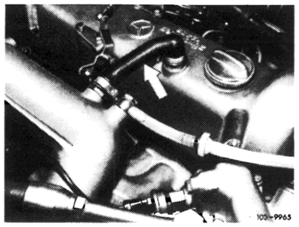
At higher speeds, blow-by gases and crankcase vapors additionally reach the rubber gaiter upstream of the throttle valve, from where they enter the combustion chambers with the induction air (arrows).
Engines 615, 616, 617
Injection pump with mechanical governor
The engine blow-by gases and crankcase vapors flow through the connecting pipe in the valve cover and pass straight into the intake manifold, from where they reach the combustion chambers with the induction air.
Engine 617 in type 115.1
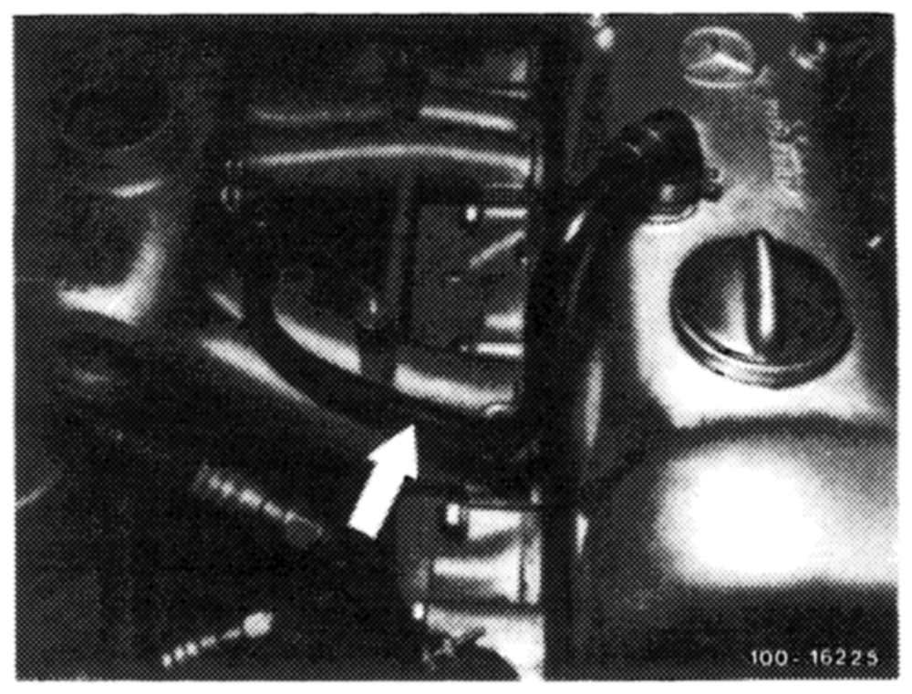
Engine 617 in type 123.1